The spectrometer, and in particular its image slicer, is used over a large wavelength range. The photometer pixel size of 9.4x9.4 arcseconds is a compromise between resolution at short wavelengths and observing efficiency (mapped area) at long wavelengths. The principle of integral field spectroscopy is illustrated in Figure 2.6. Full spatial sampling requires a fine raster with the satellite, for spectral line maps with full spatial resolution. For the sensitivity calculation this is neglected as the line flux will always be collected with the filled detector array.
It was confirmed during the Performance Verification Phase that no flux is lost in the integral-field unit, i.e. point source flux can be fully recovered from a single pointing if the source photocenter is on the central spaxel. Although the observed noise level is varying over the 5x5 field-of-view, the flux can be recovered by integrating over the neighbouring spaxels.
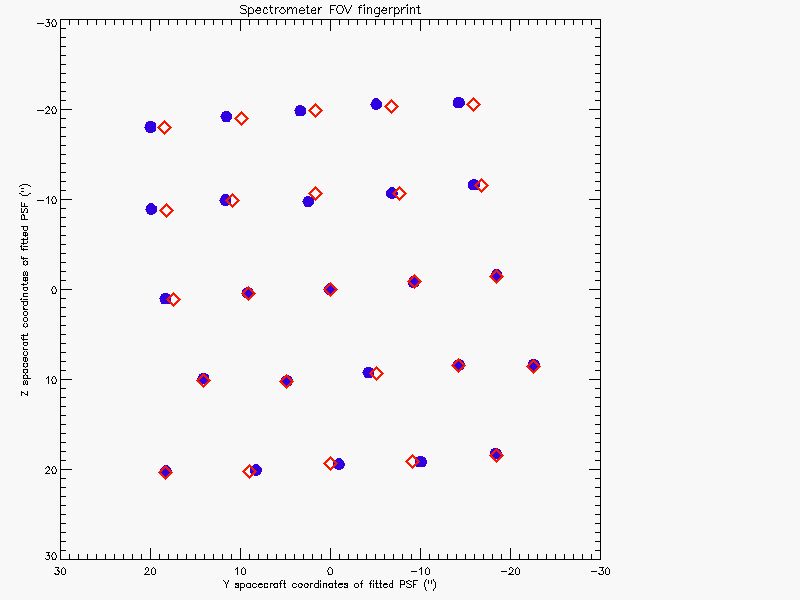
The spatial calibration of the PACS spectrometer section consists of the detailed characterization of the relative locations on the sky of the 5×5 spatial pixels (“spaxels”) in the blue and red sections and for all operational chopper positions (±3’, ±1.5’, ±0.5’, 0’). Detailed extended rasters on point sources (HIP21479 and Neptune) have been carried out during the Performance Verification Phase at a few wavelengths and the resulting spaxel geometries are stored as calibration files within the data processing environment (HIPE). Figure 4.6 shows, as an example, the result for chopper position zero in relative spacecraft units with respect to the virtual aperture of the PACS spectrometer, which is defined as the central pixel of the blue field of view. Asymmetrical optical distortions between chopper on and off positions cause unavoidable slight misalignment (smaller than 2") for individual spaxels between spacecraft nod A and B within the double differential data acquisition scheme.
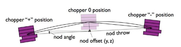
As shown on Figure 4.7 the apparent field-rotation becomes larger with increasing chopper throw.