Detailed description of "parent AOTs" from which the SPIRE PACS Parallel Mode AOT is derived can be found in the corresponding Observers' Manuals (see Section 3.2.1 of the SPIRE Observers' Manual and Section 4.1.3.2 of the PACS Observers' Manual).
The Parallel Mode AOT is offered with only one observing mode: scanning. It is the only compatible mode for operating SPIRE and PACS simultaneously: in fact, scan mode is the only option for both SPIRE and PACS to map large areas of the sky, even when they are operated alone.
The scanning strategy has been optimized for both instruments. Scan maps are performed by slewing the spacecraft at a constant speed along parallel lines to cover a large area. The lines follow great circles on the sphere which approximates parallel lines over short distances. When finishing a scan leg, the spacecraft has to perform a turn maneuver and continue observing along the next scan leg in the opposite direction: the time required for this turn is about half a minute. Note that scan mapping does not make use of chopping, being the signal modulation provided by the spacecraft motion.
Two scan speeds are offered: the fast mode applies 60 arcseconds per second, the slow mode is performed at 20 arcseconds per second. Applying the fast mode (default value), PACS PSF is degraded due to on-board data averaging and detector memory effects.
The Parallel Mode AOT does not allow to do cross-scans in a single observation. However, it is strongly suggested to perform two scan maps of the same area, one with nominal coverage and the other with orthogonal coverage, in order to remove more efficiently the stripping effects due to the 1/f noise and to get better coverage redundancy, especially for SPIRE. For this purpose two AORs shall be concatenated in HSpot to be performed with a different scan direction. An example of the better coverage achievable using cross-scans is presented in Figure 2.8.
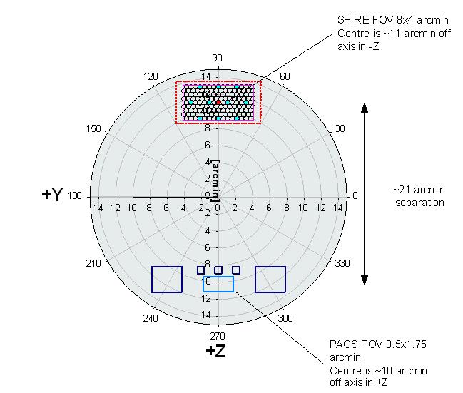
Figure 2.1. PACS and SPIRE footprints overlayed on the Herschel focal plane image. The field-of-views of the two instruments are separated by 21 arcminutes respectively.
As the SPIRE arrays are not fully filled, the telescope scans in Parallel Mode are carried out at +42.4º ("Nominal" scan direction) or -42.4º ("Orthogonal" scan direction) with respect to short axis of the arrays (angle from instrument +Z-axis to +Y-axis, see Figure 2.1). In order to provide homogeneous coverage over the mapping area and to optimize PACS performances in the two scan directions (see Section 4.1.3.2 of the PACS Observers' Manual), the step size between consecutive lines is 168" when scanning in the "Nominal" direction and 155" when scanning in the "Orthogonal" one. This small step size for SPIRE (being 348" the default one SPIRE-only large scan maps, see Section 3.2.1 of the SPIRE Observers' Manual) results in a high oversampling factor and a gain in sensitivity, without compromising map uniformity.
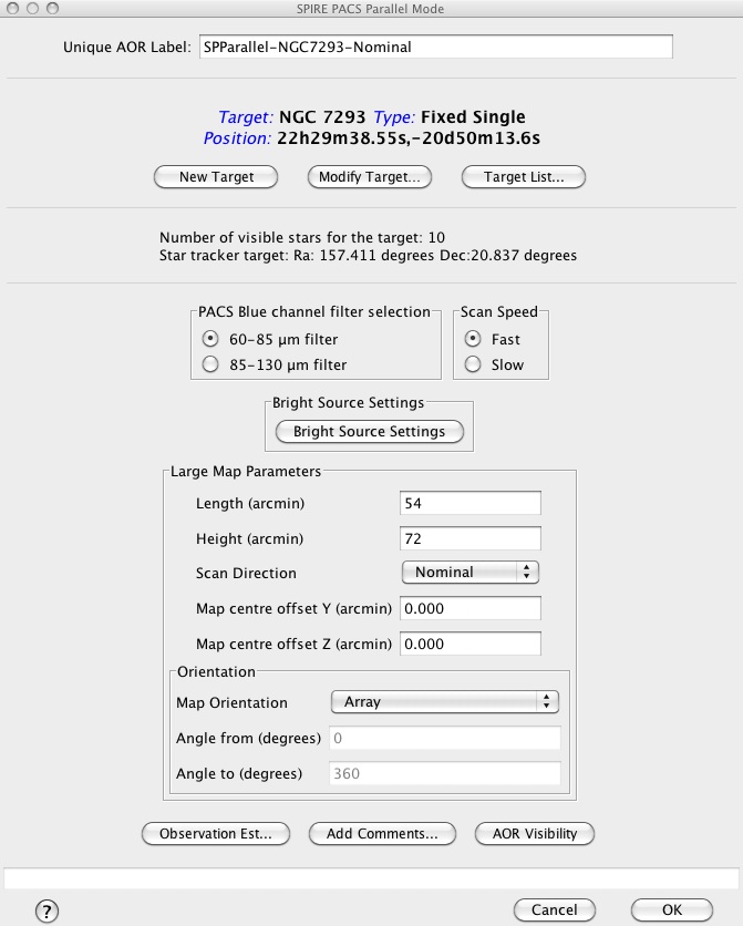
When selecting "SPIRE PACS Parallel Mode" from the "Observation" menu in HSpot (see Chapter 14 of the HSpot Users' Guide), a window like the one shown in Figure 2.2 appears on the screen.
As a first step, the PACS band has to be selected in the blue channel (60-85 µm or 85-130 µm). The other four Parallel Mode bands are fixed.
In the second step, selecting the scan speed the observer could have control over the sensitivity of the measurement. Note that there is no possibility to repeat Parallel Mode maps within one single observation request (AOR) to enhance the survey depth.
![[Note]](../../admonitions/note.png) | Note |
|---|---|
| The depth of observation in Parallel Mode mode can be controlled by three ways: (i) adjust scan speed; (ii) add "Nominal" and "Orthogonal" coverages on the same area of the sky; (iii) repeat AORs. |
The dimensions of the area to be covered is set by the length and height of the common SPIRE-PACS survey area (see Figure 2.3). The figure illustrates how the common SPIRE-PACS survey area - the grey box - is actually built up. The number of scans required to cover the common area is higher than would be required in a single instrument coverage. The number of extra scans and the required length of the scan legs both depend on the scan angle and the footprints separation. Taking into account the 42.4º scan angle and the fixed 21' separation of the SPIRE and PACS focal planes' footprints on the sky, the Parallel Mode observations perform five or six extra scans and extend the scan leg length with 22' respectively. Hence, the actual area observed with each instrument will be bigger than what was requested.
| Note |
|---|---|
| Using the SPIRE Photometer AOT, the Parallel Mode settings can be reproduced in scan map mode simply enlarging the requested area by ~15' in both length and height. This applies to PACS scan map mode too: however, in this case the observer must set a scan step of 168" and +42.4º orientation angle in "Array" or "Array with sky constraint" reference frame to get the same Parallel Mode "Nominal" scan direction coverage. The scan step must be set to 155" and the orientation angle to -42.4º to reproduce the Parallel Mode "Orthogonal" scan direction coverage. |
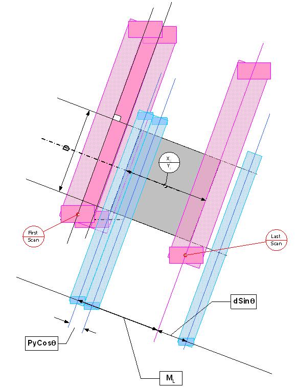
Figure 2.3. Illustration of Parallel Mode scanning scheme. The grey area is the common SPIRE-PACS survey field what the observer specifies in HSpot. The scanning angle with respect the arrays' short axis is 42.4º. Red colour represents the SPIRE scanning path, blue colour is used for PACS.
The centre of the common survey area is at the coordinates given by the target position, unless an offset along the axes Y or Z of the spacecraft coordinates is given. The map size along a scan leg can be specified by the map "Length" parameter. In perpendicular direction, the common survey size is defined by the "Height" parameter. In case the scan direction is set to "Orthogonal", then the observer has to change the "Length" and "Height" parameters and the spacecraft will perform an observation along -42.4º scan angle over the same survey area specified for the "Nominal" direction. The pairs of nominal and orthogonal AORs can be concatenated in HSpot (see further details in the HSpot Users' Guide).
An illustration of how a Parallel Mode AOR footprint is visualized in HSpot can be seen in Figure 2.4 and in Figure 2.5. Pink represents the PACS and green the SPIRE footprint: the observer requested common survey area is painted by both instruments. SPIRE and PACS coverage maps as taken from real observations is shown in Figure 2.6, Figure 2.7 and Figure 2.8.
![[Tip]](../../admonitions/tip.png) | Tip |
|---|---|
| It is recommended to concatenate Parallel Mode AORs if the same target applies for all measurement in a sequence. In such a group of observations the observatory overhead will be charged only once and HSpot will render this time to the first AOR of the concatenation chain. |
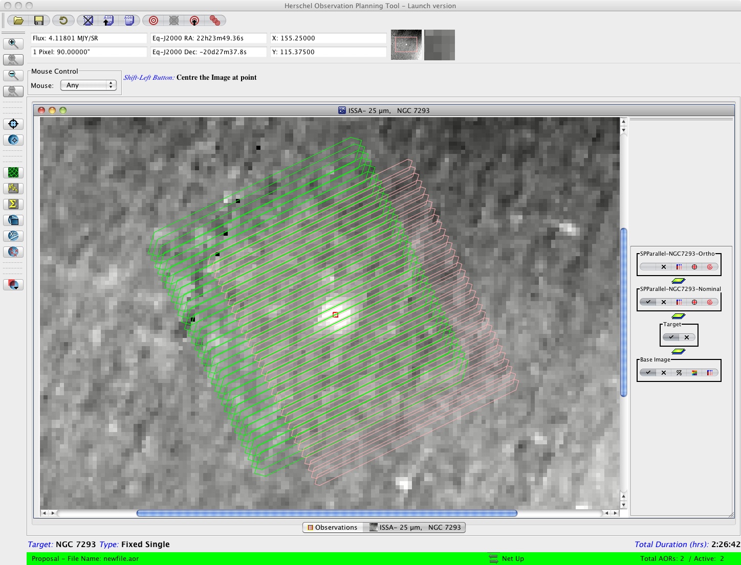
Figure 2.4. Parallel Mode footprint image example as displayed in HSpot. NGC 7293 is imaged in "Nominal" scan direction with a coverage area of 54'x72'. A comparison between observer's requested area and real instrument coverages is presented in Figure 2.6.
Three optional parameters are available:
- "Bright Source Setting": enabling this setting (disabled by default), settings of SPIRE and PACS photometers will be optimized to observe bright sources, without saturating their dynamic range, but at the cost of sensibly increasing the instruments' noise. Depending on the science case, the observer might want to enable it for one or both instruments. Please refer to the SPIRE Observers' Manual and the PACS Observers' Manual for applicable flux thresholds.
- "Map centre offset": by default, the common SPIRE-PACS coverage is centered on the target coordinates. The observer has the option to apply an offset to the centre, given in spacecraft coordinates (Y,Z) in arcminutes.
"Orientation": as the map is carried with a specific angle of the arrays and because the orientation of the array on the sky changes as Herschel moves in its orbit, then the actual coverage of the map will rotate about the requested centre of the map except for sources close to the ecliptic plane. However, in order to cover specific rectangular (elongated) areas in the sky, a constraint on the orientation of the scan map in the sky can be introduced by selecting a range for the "map position angle", i.e. the angle from the celestial equatorial North to the scan line direction, counted positively East of North. This corresponds to the option "Array with Sky Constraint" in HSpot.
Setting a Map Orientation constraint means that your observation will not be able to be performed during certain periods, hence the number of days that your observation can be made will be reduced from the number of days that the target is actually visible. In setting a constraint, the observer needs to check that it is still possible to fit the observation within a visibility window or if the orientation constraint blocked out all dates. Note also that parts of the sky do not change their orientation with respect to the array and therefore it is not possible to set the orientation of the map in certain directions (close to the ecliptic plane) as the array is orientated in a restricted direction on the sky.
| Note |
|---|---|
| Setting constraints on when the observation can be performed make scheduling and the use of Herschel less efficient, hence the observer will be charged extra overheads to compensate (see Herschel Observatory Manual). |
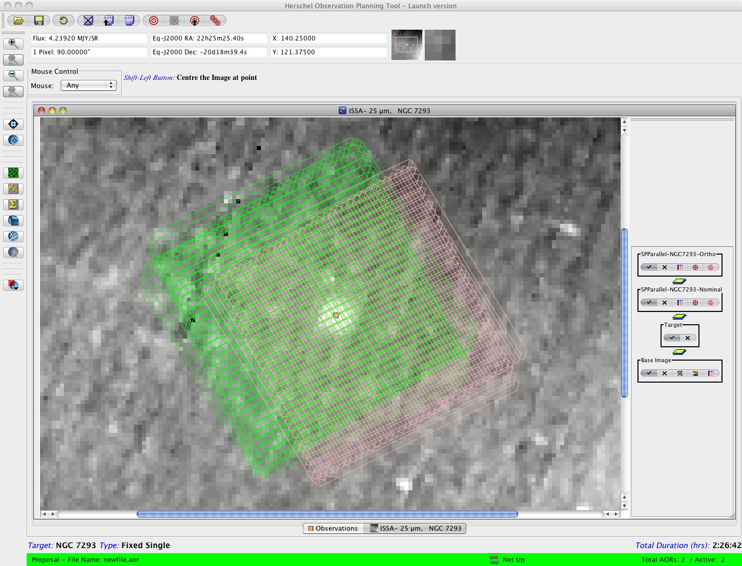
Figure 2.5. Parallel Mode footprint image example as displayed in HSpot. NGC 7293 is imaged in "Nominal" plus "Orthogonal" scan directions. However, the "Length" and "Height" parameters are the same in the 2 AORs (instead of being inverted): the result is that the area covered by both instruments, in both directions, is only 54'x54' (see Figure 2.7).
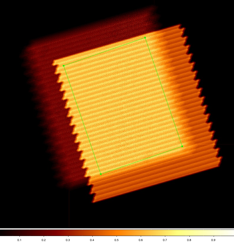
Figure 2.6. SPIRE (darker area, shift to left) and PACS coverage maps, normalized to 1, as obtained from observation of NGC 7293 in "Nominal" scan direction only. Overplotted in green is the original observer requested area of 54'x72'.
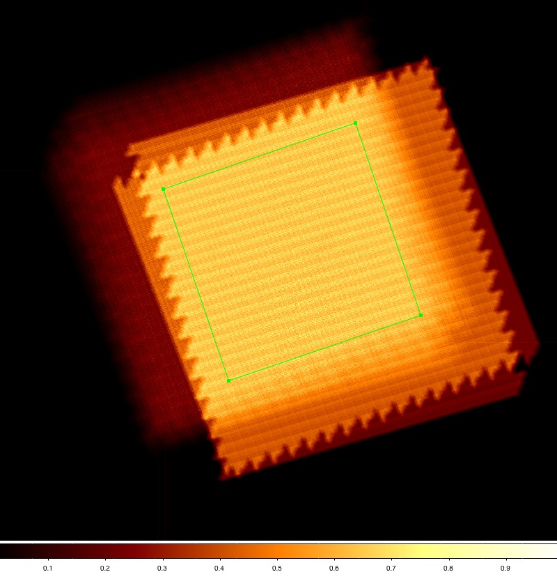
Figure 2.7. SPIRE (darker area, shift to left) and PACS coverage maps, normalized to 1, as obtained from observation of NGC 7293 in "Nominal" and "Orthogonal" scan directions. Overplotted in green is guaranteed area observed by both instruments, in both scanning direction. Since the "Length" and "Height" parameters were the same in the 2 AORs, this area corresponds to a square of 54'x54'.
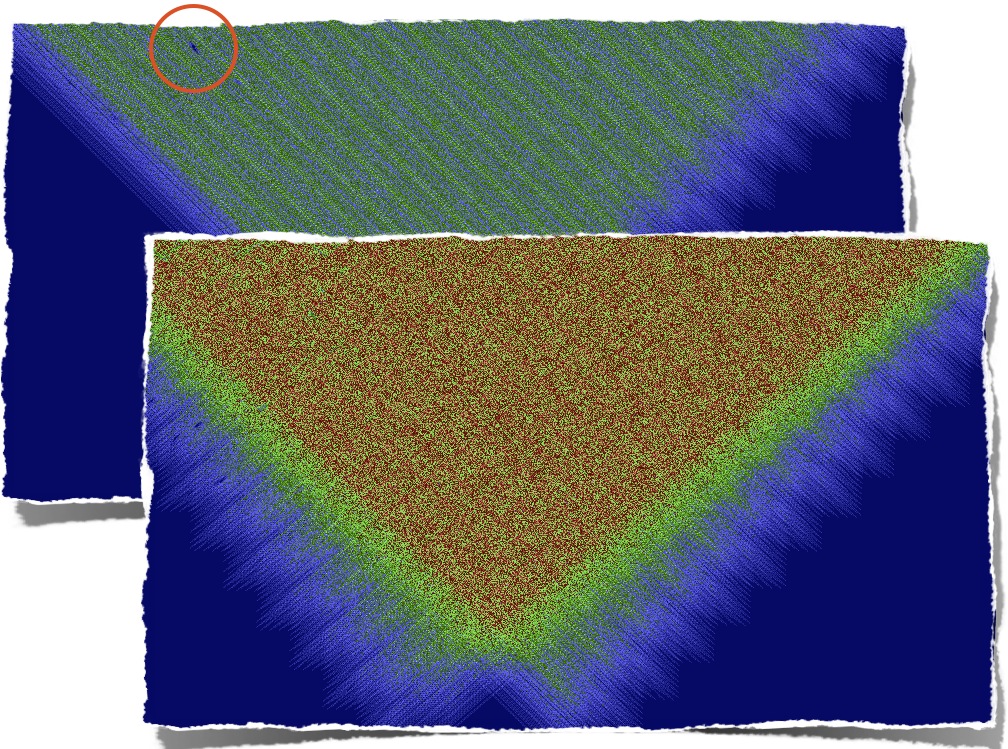
Figure 2.8. SPIRE coverage comparison between single-scan (figure behind) and cross-scans (figure in front) Parallel Mode observations. Note the better coverage of the latter, especially if some pixels have been masked out during data reduction (circled area).
Table 2.2. Observer input parameters for SPIRE PACS Parallel Mode AOT.
Parameter name | Signification and comments |
|---|---|
Filter | Which of the two filters from the PACS blue channel to use (60-85 µm or 85-130 µm). |
Map Orientation | The reference frame for the scan map orientation, either "Array" or "Array with Sky Constraint". This can be entered, by selecting a range of map orientation angles for the observation to take place. |
Angle from/to | The constraint on map angle is the angle measured from the equatorial North to the direction of the scan leg calculated East of North and towards the scan direction of the map's first scan leg. |
Scan speed | Slew speed of the spacecraft: fast mode (60"/s) or slow mode (20"/s). |
Length | Length of the common survey area parallel the scan direction in arcminutes: the maximum length is 1173'. |
Height | Size of the common survey area in perpendicular direction in arcminutes: the maximum height is 231'. |
Scan Direction | This parameter defines the scan angle along which the spacecraft builds up the scan legs. In "Nominal" direction the scan angle is 42.4º and the scan leg separation is 168", in "Orthogonal" direction the angle is set to -42.4º and the scan leg separation to 155". |
Map centre offset Y | The offset of the map centre from the input target coordinates along the Y axis of the spacecraft coordinate system, in arcminutes. |
Map centre offset Z | The offset of the map centre from the input target coordinates along the Z axis of the spacecraft coordinate system, in arcminutes. |