Even though the chop-nod point source mode is still available in HSpot and perfectly calibrated, we discourage to use this mode for science observations as it is less sensitive than scan mapping for the same AOR execution time. We recommend to use the mini-scan map technique in all science cases related to point-sources, compact sources and also in cases of faint extended emission around point-sources.
For more information we refer to the technical note: PACS Photometer - Point/Compact Source Observations: Mini Scan-Maps and Chop-Nod
The point-source photometry observing mode makes use of a chop-nod technique and shall be used for sources that are significantly smaller than a single matrix (50 arcsec x 50 arcsec), i.e. mostly point sources .
The PACS photometer chop-nod point-source mode uses the PACS chopper to move the source along the Y spacecraft axis by about 50 arcsec, corresponding to the size of about 1 blue/green bolometer matrix or the size of about half a red matrix, with a chopper frequency of 1.25 Hz. The nodding is performed by a satellite movement of the same amplitude , but perpendicular to the chopping direction, i.e. along the Z spacecraft axis, to compensate for the different optical paths, as illustrated in Figure 5.7.
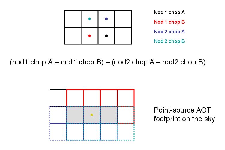
Figure 5.7. Source positions in point-source photometry AOT. Sketch showing the source positions as a function of the nod and chopper positions. The Y-axis is to the left, the Z-axis to the top. Chop positions are defined by the internal chopper, while nod positions are defined by the satellite pointing. Dithering at each chopper position, performed with the internal chopper is not represented.
On each nod-position the chopper executes 3x25 chopper cycles. The 3 sets of chopper patterns are either on the same array positions (no dithering) or on 3 different array positions (dither option). In the dither-option the chopper pattern is displaced along Y-direction (along the chopper direction) by about 8.5 arcsec (2.66 blue pixels or 1.33 red pixels). Each chopper plateau lasts for 0.4 second (16 readouts on-board) producing 4 frames per plateau in the down-link. The full 3x25 chopper cycles per nodposition are completed in less than 1 minute. The pattern is repeated on the second nod-position. In case of repetition factors larger than 1, the nod-cycles are repeated in the following way (example for 4 repetitions): nodA-nodB-nodB-nodA-nodA-nodB-nodB-nodA to minimise satellite slew times. The minimal duration of this observing mode with calibration and slew overheads is 5.5 min, including the fixed overhead of 3 min for the initial slew to target.
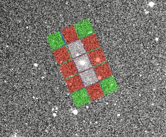
An example of an exposure map as generated by the HSpot exposure map tool for the blue channel is shown in Figure 5.8 .
The chop-nod point-source mode works fine for bright sources and empty fields. But the achieved sensitivities are worse by a factor 1.5-2 compared to the pre-flight prediction and the mini-scan map mode, (see Section 5.2, “Mini-scan map mode”) because the chopping frequency is not high enough to remove the 1/f noise at 3 Hz.
Despite the degraded sensitivity this mode has advantages for intermediately bright sources in the range 50 mJy to about 50 Jy: a small relative pointing error (RPE) of 0.3 arcsec and high photometric reliability and reproducibility .
In the point-source photometry mode the properly imaged field (i.e. with chopping and nodding) is rectangular : about 52 arcsec x 2.5 arcmin (see Figure 5.8). The user might therefore want to exclude some position angles of the chopping direction to avoid chopping into a bright close-by infrared source.
For this purpose an interval of chopper avoidance angles can be entered in HSpot. The chopper avoidance angle is counted positive east of north, i.e. counterclockwise in the sky, from the north to the direction of the object to avoid, i.e. the +Y spacecraft axis. As the chopper cannot rotate, this effectively defines an avoidance angle for the satellite orientation. Hence it is a scheduling constraint.
The range of position angles that will be available for a given target can be visualized with the AOR footprint overlay functionality for different observing dates in the visibility windows. The exact angle values can be determined with the 'Herschel Focal Plane' overlay functionality.
![[Note]](../../admonitions/note.gif) | Note |
|---|---|
| The position angle returned by HSpot in the AOR overlays is the angle from the north to the spacecraft +Z axis counterclockwise, perpendicular to the chopping direction. Therefore the chopper avoidance angle can be derived from the position angle by adding 90 degrees (modulo 180 degrees). |
![[Warning]](../../admonitions/warning.gif) | Warning |
|---|---|
| For pointings close to the ecliptic plane, the position angle is constrained to a very narrow range of values : the inclination of the ecliptic plane, and the chopping direction is perpendicular to the ecliptic plane. For such targets, the chopping avoidance angle is at best unnecessary, and at worse renders the observation impossible. For observations at higher ecliptic latitudes, the user shall check that the range of chopping avoidance angles is compatible with the position angles in the visibility windows. |
| Warning |
|---|---|
| When a chopping avoidance angle is set, the constraint is not yet fed back in HSpot to the visibility calculation, so that the Herschel visibility windows are not affected by that constraint. The user is thus invited to assess himself the impact on the visibility of that constraint. |
Table 5.2 lists the user inputs required in HSpot.
Table 5.2. User input parameters for the point-source AOT mode
Parameter name | Meaning and comments |
|---|---|
Filter | which of the two filters from the blue channel to use. In case observations in the two blue filter bands are required to be performed consecutively, two AORs shall be concatenated. |
Dithering | On (dithering enabled) or Off (dithering disabled). A fixed dithering pattern is applied with an amplitude of 2.33 (blue channel) pixels with the chopper. This is intended to improve the flat-field accuracy and to produce better photometric results for faint targets. |
Chopper avoidance angle | Interval of position angles for the chopper avoidance zone, modulo 180 degrees. The position angle is counted positive east of north, i.e. counterclockwise in the sky, from the north to the direction of the object to avoid. |
Repetition factor | Number of AB nod cycles to adjust the absolute sensitivity, maximum 120 |
Source flux estimates | Optional: point source flux density (in mJy) or surface brightness (in MJy/sr) for each band. It is used for signal-to-noise calculations and to change the ADC to low-gain if the flux in one of the two channel is above the ADC saturation threshold. See Section 5.4 for more details. |