Table of Contents
The PACS instrument comprises two sub-instruments which offer two basic and and mutually exclusive modes in the wavelength band 55-210 µm :
Imaging dual-band photometry (60-85 µm or 85-125 µm and 125-210 µm) over a field of view of 1.75'x3.5', with full sampling of the telescope point spread function (diffraction/wavefront error limited)
Integral-field spectroscopy between 51 and 220 µm with a resolution of ~75-300km/s and instantaneous coverage of ~1500 km/s, over a field of view of 47"x47".
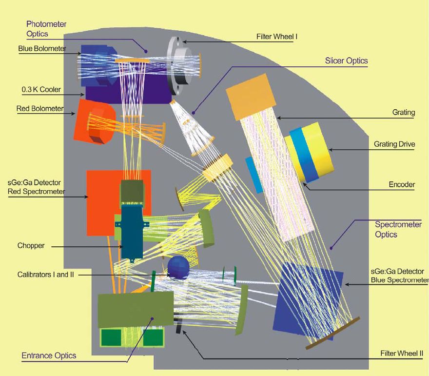
Figure 2.1. Optical layout. After the common entrance optics with calibration sources and the chopper, the field is split into the spectrometer train and the photometer trains. In the latter a dichroic beam splitter feeds separate re-imaging optics for the two bolometer arrays. In the spectrometer train, the image slicer converts the square field into an effective long slit for the Littrow-mounted grating spectrograph. The dispersed light is distributed to the two photoconductor arrays by a dichroic beam splitter which acts as an order sorter for the grating.
Figure 2.1 shows how the functional groups are distributed in the spatial instrument envelope.
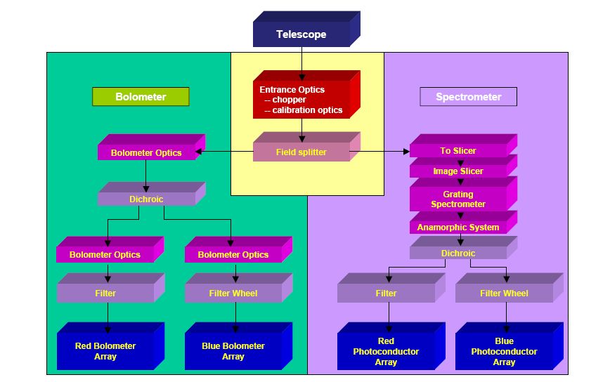
Figure 2.2 shows an optical circuit block diagram of the major functional parts of PACS. At the top, the entrance and calibration optics is common to all optical paths through the instrument. On the right, the spectrometer serves both, the short-wavelength (“blue”), and long-wavelength (“red”) photoconductor arrays. A fixed dichroic beam splitter separates blue from red spectrometer light at the very end of the optical path. On the left, the bolometer fixed dichroic beam splitter comes before the blue and red imaging branches since they require different magnification. Directly in front of their baffle enclosures the blue detectors have filter wheel mechanisms which contain the band pass filters for short wavelength photometry, and the order selection band passes for 2nd and 3rd order operation of the grating spectrometer, respectively.
The focal plane sharing of the instrument channels is shown in Figure 2.3. The photometric bands, which can be observed simultaneously, cover the same field-of-view. The field-of-view of the spectrometer is offset from the photometer field (see Figure 2.3). However, this has no effect on the observing efficiency.
The focal plane unit provides photometric and spectroscopic capabilities through five functional units :
common input optics with the chopper, calibration sources and a focal plane splitter;
a photometer optical train with a dichroic beam splitter and separate re-imaging optics for the two short-wavelength bands (60-85 µm/ 85-125 µm) selectable via a filter wheel and the long-wavelength band (125-210 µm), respectively;
two bolometer arrays with cryogenic buffers/multiplexers and a common 0.3 K sorption cooler;
a spectrometer optical train with an image slicer unit for integral field spectroscopy, an anamorphic collimator, a movable diffraction grating in Littrow mount, anamorphic re-imaging optics, and a dichroic beam splitter for separation of diffraction orders. The blue channel contains an additional filter wheel for selecting its short or long wavelength part;
two photoconductor arrays with attached cryogenic readout electronics (CRE).
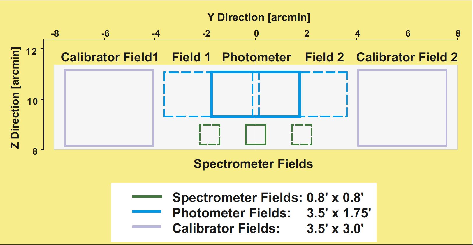
PACS focal plane usage. Long-wavelength and short wavelength photometry bands cover practically identical fields-of-view. The spectrometer FOV is offset in the -Z direction (closer to the optical axis of the telescope). Chopping is done along the Y axis (left-right in this view) and also allows observation of the internal calibrators on both sides of the used area in the telescope focal plane. The maximum chopper throw for sky observations is ~3.5 arcmin for photometry and 6 arcmin for spectroscopy. In photometry, object and reference fields are almost touching at 3.5 arcmin throw.
Figure 2.3. PACS field-of-view footprint in the telescope focal plane.