Selecting "SPIRE PACS Parallel Mode" from the "Observation" menu gives the AOT for photometry with SPIRE and PACS simultaneously. The first step is to define a target, see Section 6.3. On the AOT screen (shown in Figure 14.1) you see "PACS Blue channel filter selection", "Scan Speed" and "Large Map Parameters" boxes along with the button "Observation Estimaties" these are described in the following sections.
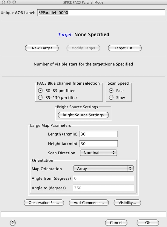
This option allows to select the PACS Blue channel, the choice is from the 60-85 µm or 85-130 µm filter. This AOT automatically produces data from the 3 SPIRE bands and the PACS red channel as well.
The speed at which the telescope is scanned can be chosen, between fast (60"/s) and slow (20"/s) speeds.
By clicking on the "Bright Source Settings" button a window is popping up. Selecting "Yes" will induce a change in the detector settings and sensitivity of the observation for the instrument selected. You can control SPIRE and PACS separately, depending on the science case the observation is designed for. By default, photometers are configured in sensitive mode. Please check applicable flux tresholds in the SPIRE PACS Parallel Mode Observers' Manual.
The map is made by scanning the telescope to move the fields of views of SPIRE and PACS over the requested area of sky. Due to the large offset of the fields of views of SPIRE and PACS (21 arcminutes) this mode is extremely inefficient for small maps, as excess area has to be mapped by each instrument so that both instruments will cover the user requested area fully (see the SPIRE PACS Parallel Mode Observers' Manual for details). The size of the area to be mapped, centred on the target coordinates, is entered in the "Length" and "Height" boxes in arcminutes. The "Length" corresponds to the dimension of the map in the scan direction. Note that the actual scan legs made by the telescope will be longer than this to ensure that both SPIRE and PACS cover this area properly. The "Height" option corresponds to the dimension of the map in the cross-scan direction, again this dimension will be increased to ensure proper coverage with both instruments. A choice of scan directions, "Nominal" or "Orthogonal", is available from the "Scan Direction" pulldown menu. For details about this option see the SPIRE PACS Parallel Mode Observers' Manual.
The maximum permitted length of a scan is 1173 arcminutes (19.55 degrees), while the maximum permissible with is 231 arcminutes (3.85 degrees). Prior to a slight change in the way that Parallel Mode observations are taken made in April 2010, HSpot permitted the slightly greater width of 232 arcminutes: old AORs that have been cloned will thus now give an error unless this value is modified to the new limit - the practical consequences of this change for map coverage are insignificant.
Like the SPIRE and PACS mapping, the SPIRE PACS Parallel Mode also has the option to constrain the direction of the scan legs. Maps are made at a specific angle (depending on the selection of nominal or orthogonal) to the instrument arrays. The area mapped depends on the day that the observation is scheduled for high ecliptic latitudes, this "Orientation" option can be used to restrict the possibilities by selecting "Array with Sky Constraint" and specifying a range of angles. This equates to a period within which the observation can be scheduled hence the following warning is given with the option Array with Sky Constraint is selected:
![[Warning]](../../admonitions/warning.gif) | Warning |
|---|---|
| Specifying the map orientation constraint places restrictions on when the observation can be scheduled. The observatory overhead for this observation will be 600s. These constraints might reduce the chance that your observation will be carried out, especially targets at low ecliptic latitudes could be inaccessible for certain chopper or map angles. Are you sure that this constraint is essential? (You may check your observation's footprint orientations by clicking in the HSpot menu: Overlays -> AORs on current image... see the Observers' Manual for examples). |
Once the warning has been understood and dismissed by pressing OK, the "Angle From" and "Angle To" values, between which the "Length" dimension of the map should lay, can be given in degrees east of north can be entered to a precision of one degree. To have the "Length" dimension lie in approximately the north-south direction one should remember to enter a number lower than 360 in the "From" box and one greater than 0 in the "To" box. See the SPIRE PACS Parallel Mode Observers' Manual for a worked example.
On pressing the "Observation Est..." button the duration of the observation is estimated (calculated) and a pop-up displays the results (see Figure 14.2 for the resulting screen for a Fast Scan Speed map of 120 by 120 arcminute.
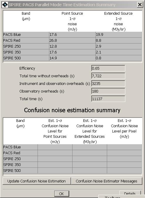
The Observation Time Estimation returns the point source 1-sigma noise (mJy) and the extended source 1-sigma noise (MJy/sr) of the observation for each wavelength band.
| Warning |
|---|---|
| The PACS sensitivity for extended emission is underestimated by ~30% in the blue and green bands, and by a factor ~2 in the red band. Proper PACS estimates from in-flight measurements are returned in PACS prime scan maps only. |
![[Note]](../../admonitions/note.gif) | Note |
|---|---|
| the 1-sigma noise for SPIRE refers to beam areas, while the PACS noise is per native pixels, (i.e. 3.2" x 3.2" in the blue channel and 6.4"x6.4" in the red channel), hence the large differences between the 2 instruments. |
Next, the break down into observing time and overheads is displayed:
Efficiency: this is the ratio of the user requested area to the total area map by SPIRE, it is an indication of the how much extra area is needed to map the user area with both instrument.
Total time without overheads (s): This is the time taken to map the total area covered by the observation. It does not include instrument and observations overheads which are accounted for in the next entry.
Instrument and observation overheads (s): the calibration time and dead time associated with the observation (such as instrument set up time and telescope turn around time).
Observatory overheads (s): the slew overhead implicit in every observation.
Total time (s): the sum of the above time contributions.
The "Details" button at the button of the window pops up a window with details messages about the AOR. To display one or more message levels select the relevant box(es). Message level 1 gives indicates how the observation is built up. Message level 3 gives parameters of the observation such as the angle at which the array is scanned (patt), the distance between scan leg centres (d2, in arcseconds), the "required scan length" in arcseconds (increased from your input to get as even coverage as possible over requested area), and the "required number of scan lines in map" needed to cover the area.
The breakdown of calculated confusion noise is given in a table at the bottom of the "SPIRE PACS Parallel Mode Time Estimation Summary" screen (see Figure 14.2). It indicates the confusion noise specific for the AOR configuration (see the Herschel Confusion Noise Estimator Science Implementation Document for details). When the window pops up this table is empty, in order to get a confusion noise estimation the "Update confusion noise estimates" button has to be pushed.