Table of Contents
In this AOT the PACS spectrometer is operating for observations of individual spectral lines. Depending on the requested grating order, the short-wavelength array observes in the 55-73 micron, or 73-98 micron band, while the long wavelength red array observes in the 103-210 micron band. For improved flat-fielding, the grating will be scanned by a number of discrete steps around the spectral line central wavelength, such that drifts in detector responsivity between individual pixels are eliminated. These grating scans provide a short spectrum covering ~1500 km/h with a resolving power of ~1700 in its highest resolution for each line and for each of the five by five spatial pixels. Background subtraction can be achieved either through standard chopping/nodding (with faint or bright lines option), or through 'wavelength-switching' techniques of the grating mechanism (especially for line measurements of bright extended sources or point sources in crowded fields). The observer can select chopping/nodding in combination with one of the three observing modes: "pointed", "pointed with dither" and "mapping", while wavelength switching is being offered in the "mapping" mode only.
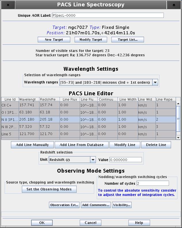
The "Wavelength Settings" part of the PACS Line Spectroscopy start-up screen provides the observer with the opportunity to specify a set of spectral lines to observe within a single AOR. The main component of this functionality is the "PACS Line Editor" table which is where spectral line information is held. Before the observer provides table entries, the applicable wavelength ranges have to be specified.
The user selects the applicable wavelength ranges (defined by the grating diffraction orders) via the first pull-down menu. There are two possibilities:
Option 1 - "[73-98] and [103-210] microns (2nd + 1st orders) " - default option
Option 2 - "[55-73] and [103-210] microns (3rd + 1st orders)"
As a result of the selection, the (redshifted) wavelengths of line centres have to be specified in the "PACS Line Editor" table, either within the 73-98 and 103-210 microns band, or within the 55-72 and 105-210 microns band.
![[Note]](../../admonitions/note.gif) | Note |
|---|---|
| The PACS spectral coverage is not continuous over the entire 55-210 microns range, it has a gap from 98 to 103 microns. Spectral lines cannot be requested in this unsensitive range. |
![[Note]](../../admonitions/note.gif) | Note |
|---|---|
| As it is indicated in the options above, irrespective the blue order selection spectral lines can be always requested in the 103-210 microns band (1st diffraction order) of the red spectrometer array. |
![[Tip]](../../admonitions/tip.gif) | Tip |
|---|---|
| The observer has a choice of creating an observation of spectral lines located along the entire PACS wavelength range by grouping AORs. In this case at least two AORs have to be filled with flipped grating order options. See Section 6.5.3, “Group/Follow-on Constraints” and Section 16.2, “Timing Constraints ” (grouping and timing constraints) for further information. |
When setting up the list of spectral lines to be observed the PACS Line Editor is used. The AOT allows a maximum of ten lines to be entered into the table, although the use of "Repetition factor" parameter could result a further restriction on the number of observable lines (see below).
![[Tip]](../../admonitions/tip.gif) | Tip |
|---|---|
| If your observation requires more than the allowed number of lines consider to set up a group of AORs. See Section 6.5.3, “Group/Follow-on Constraints” and Section 16.2, “Timing Constraints ” (grouping and timing constraints) for further information. |
The table gives a summary of spectral line dependent attributes of your AOR. You cannot enter, modify or remove values in the table directly. The three buttons at the bottom of the table allow the following:
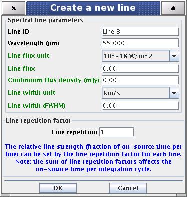
Add line manually - pressing this button allows the addition of a new spectral line in the chosen wavelength range. A "Create a new line" window is opened and the user can enter values in the enabled fields. The "Line ID" and "Wavelength" fields cannot be edited if the line is taken from a database. Once the "OK" button is pressed the spectral line settings are stored in the PACS Line Editor.
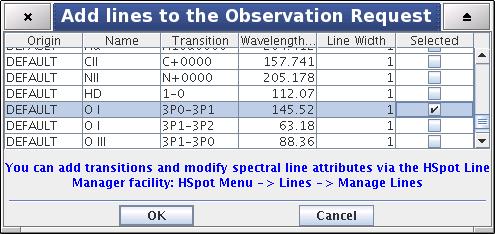
Add line from database - The selection of a given line/transition can be made via the HSpot spectral line managing system. Clicking on this button will make the "Add Lines to the Observation Request" dialogue window pop-up (see below). This dialogue allows the addition of a spectral line that is within the PACS [55-210] microns wavelength range. Once the line/transition is selected and the "OK" button is clicked the line settings are stored and a synopsis is displayed in the PACS Line Editor. Line attributes will show default settings in the table, you have to click on "Modify Line" to reset parameters.
Modify line - This button allows spectral line settings to be modified after they have been created with the "Add line manually" or "Add line from database" functionalities noted above. The window popping-up is identical to the "Create a new line" dialogue in all functionalities (see below).
Delete line - Allows the deletion of a spectral line. Click on the table entry holding the spectral line to highlight it then hit the "Delete" button to remove it. Deleting a line has no effect on other lines in the table. Default line IDs will not change for already configured lines.
The "Add Lines to the Observation Request" dialogue is a shopping basket which filters PACS detectable transitions from the HSpot "Manage Lines" facility (see Section 18.1, “Managing Lines”).
The "Add Lines to the Observation Request" dialogue has some rules applied to it:
Only one line may be selected in a single dialogue. To retrieve additional spectral lines, click on again the "From Database" check box and repeat the procedure for the next line in the table.
If your "Manage Lines" window does not contain any user defined lines that fall in the specified PACS wavelength range the "Add Lines to the Observation Request" dialogue will open containing the default lines only. You should click on "Cancel" and fill your line database with appropriate transitions through the "Manage Lines" dialogue (see Section 18.1, “Managing Lines”).
![[Note]](../../admonitions/note.gif) | Note |
|---|---|
| Default lines included in the "Add Lines to the Observation Request" dialogue provides a handful set of most often requested strong lines. Some of these transitions (mostly atomic lines) are not included in the online available catalogues linked to HSpot. |
![[Tip]](../../admonitions/tip.gif) | Tip |
|---|---|
| An extended list of lines can be added to the "Add Lines to the Observation Request" window from online catalogues and/or individual line information provided by the user (see Section 18.1, “Managing Lines” and the functionalities of the "Manage Lines" dialogue). |
![[Note]](../../admonitions/note.gif) | Note |
|---|---|
| The Create a new line / Update a line dialogues include optional parameters for signal-to-noise calculation in case the observer can supply source estimates. Optional parameters are highlighted in green text in the HSpot windows. |
Mandatory parameter. A unique line identification label. It has to be at least one character different for the subsequent lines, default values are "Line 1, Line 2, ... Line 10". User defined Line Ids could contain any character string including spaces up to 40 characters. If the user removes a line from the table (see below) the Line Id will not change for the remaining set of lines.
![[Note]](../../admonitions/note.gif) | Note |
|---|---|
| If a spectral line is taken from the "Manage Lines" database (see Section 6.5.3, “Group/Follow-on Constraints” and Section 16.2, “Timing Constraints ”) then the Line Id will be copied from the database. This string can be overwritten as can default line Ids. If a line is taken from a database the user is not allowed to reset its Line Id and wavelength in the Line Editor Table. Attributes of database transitions can be changed using the "Manage Lines" functionality (see Section 18.1, “Managing Lines”). |
Mandatory parameter. The rest wavelength of the line centre. If no redshift is specified, the PACS grating will perform an up- and down scan, centred around the line's central wavelength. For about two thirds of the on-source time PACS measures the (unresolved) spectral line and about one third of the time is spend on measuring the baseline. See the PACS Observers' Manual (http://herschel.esac.esa.int/Documentation.shtml) for more information.
![[Note]](../../admonitions/note.gif) | Note |
|---|---|
|
Parameter calculated by HSpot, it appears only in the PACS Line Editor and indicates the redshifted wavelength of the line centre. The bottom pull-down menu allows the reference frame for the redshift to be input.
![[Note]](../../admonitions/note.gif) | Note |
|---|---|
|
This menu gives the flexibility to switch between physical input units supported by the PACS AOT logic. The pull-down menu allows the unit of line flux to be defined:
Option 1 - "Flux (10^-18 Watt/m^2)", default option
Option 2 - "Flux (10^-15 erg/s/cm^2)"
The "Line Flux" parameter of the Line Editor Table is interpreted in the selected units.
![[Note]](../../admonitions/note.gif) | Note |
|---|---|
| In cgs units the flux is measured in erg s^-1 which can be converted to watts, 1 watt = 1 x 10^7 erg s^-1. |
Optional parameter. User supplied line flux estimate in units specified by the "Line Flux Units" option. Line flux input is used for signal-to-noise estimation only. None of the instrument or observing mode settings can be influenced by this parameter (in later versions of HSpot this information will be used for dynamic range adjustment as well). Leaving the parameter as the default 0.0 value means the PACS Time Estimator will not perform signal-to-noise estimation (sensitivity estimates are still provided).
Optional parameter. Continuum flux density estimate at the line (redshifted) wavelength. The value of this parameter is interpreted by the PACS Time Estimator as flux density for a spectrometer resolution element. Leaving the parameter as the default 0.0 value means the PACS Time Estimator will not perform signal-to-noise estimation (sensitivity estimates are still provided).
![[Tip]](../../admonitions/tip.gif) | Tip |
|---|---|
| The PACS spectrometer spectral resolution as a function of wavelength and gration order can be found in the PACS Observers' Manual (http://herschel.esac.esa.int/Docs/PACS/html/pacs_om.html). |
This menu gives the flexibility to switch between physical input units supported by the PACS AOT logic. The pull-down menu allows the unit of line width to be defined:
Option 1 - "1 km/s", default option
Option 2 - "1 micron"
The "Line Width" parameter in the PACS Line Editor is interpreted in the selected unit.
Optional parameter. The spectral line full width at half maximum value in units specified by the "Line Width Units" pull-down menu. Line width input is used only for checking purposes. It helps the observer to ensure the specified line width fits within the predefined wavelength range hard coded in the PACS Line Spectroscopy AOT logic (see the PACS Observers' Manual (http://herschel.esac.esa.int/Docs/PACS/html/pacs_om.html) for further details). None of the instrument or observing mode settings can be influenced by this parameter. The PACS Time Estimator will perform signal-to-noise estimation for the specified line width.
![[Warning]](../../admonitions/warning.gif) | Warning |
|---|---|
| The PACS Line Spectroscopy AOT is designed to measure unresolved or narrow spectral lines. HSpot raise a warning message if the specified line is too broad for a complete profile detection in PACS Line Spectroscopy AOT. In such a case the observer should consider to measure this spectral line in PACS Range Spectroscopy AOT high sampling density range scan mode. |
Mandatory parameter. The relative line strength (fraction of on-source time per line) is taken into account by specifying the grating scan repetition factor for each line. A maximum of 10 repetitions in total can be specified in the table. For instance, in the case that 10 lines are selected, the "Line repetition" factor has to be 1 for each line; if 3 lines are selected then the total of the 3 repetition factors has to be less or equal to 10 (e.g. 4+5+1 or 2+3+3 ...). If the sum of repetitions exceeds 10 then you must either remove spectral line(s), or reduce the scan repetition factor(s).
The following considerations have to be made when specifying the repetition factor:
Each grating scan has equal duration irrespective of the observation wavelength.
The grating scan pattern is repeated for every on-source and nod position (except in wavelength switching mode).
Higher sensitivity can be achieved either by scanning one line more often within a nod position, or by repeating the nod pattern of grating repetitions more often (see "Observing mode settings"). The latter would then affect all lines in the PACS Line Editor. If you are observing only one or two lines you should consider increasing the "Line repetition" factor in the table. This is more efficient as it minimises the nod slewing overhead.
In wavelength switching mode the "Line repetition" factor has precisely the same effect as the "Nodding or wavelength switching cycles". For instance, 3 repetition of a line with 2 cycles gives exactly the same on-source time and same measurement sequence if 2 line repetition would be combined with 3 cycles.
![[Tip]](../../admonitions/tip.gif) | Tip |
|---|---|
| You can specify an observation with more than ten grating scans per pointing position by grouping AORs. |
The redshift selection menu allows the observer to make adjustments to the observing wavelength. The input can be specified either in known radial velocities or redshifts. Once any area in the PACS Line Editor is clicked on the "Redshifted Wavelength" field turns to show the wavelength to be observed.
![[Note]](../../admonitions/note.gif) | Note |
|---|---|
| If the line rest wavelength is shorter than 55 microns then HSpot will reject the line even if the redshifted wavelength fits to the valid PACS range. For such a line you need to enter directly the redshifted wavelength into the PACS Line Editor and set the redshift to default zero. |
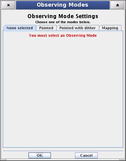
The "Observing Mode Settings" screen provides the observer with the opportunity to specify the combination of instrument modes with spacecraft pointing modes. To start the procedure just click on the "Set the Observing Modes" action button in the main AOT window. This returns a screen with the choice of observing modes, simple click on a tab to select the mode required. The default observing mode is "None selected". You must then choose another tab to validate the selected observation.
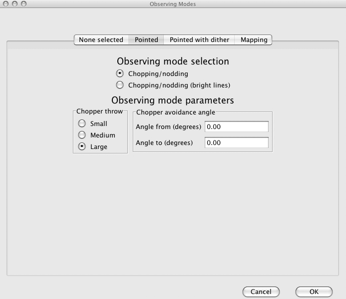
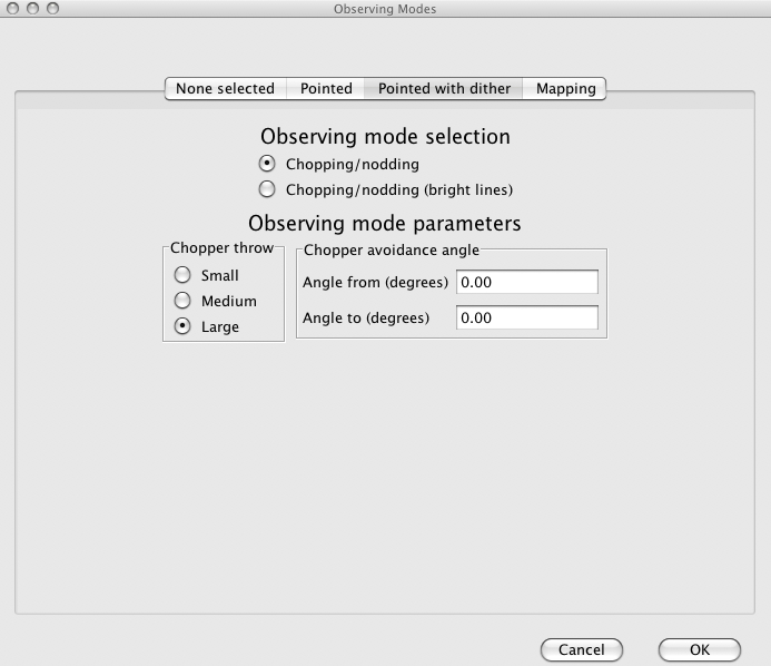
The main driver of observing modes is the pointing mode in which you wish to observe. The tab labels refer to "Pointed", "Pointed with Dither" and "Mapping" observing modes, each of them can be combined either with chopping/nodding or with wavelength switching.
On the left hand side of the observing mode settings area a text box labelled "Nodding or wavelength switching cycles" can be found. The absolute sensitivity of the observation can be controlled by entering an integer number between 1 and 100. The on-source time is increased by repeating the nodding pattern the number of times that is entered. For each of the nod positions the sequence of line scans is repeated with the relative depth specified in the PACS Line Editor (see Section 11.1.1.2, “The PACS Line Editor”). In case wavelength switching is used the on-source time is increased by switching with the grating the number of times that is entered. No nodding is applied in this latter case.
This mode is offered for taking data for a point-like object. The integral-field concept allows simultaneous spectral and spatial multiplexing, for the most efficient detection of weak individual spectral lines, with sufficient baseline coverage and high tolerance to pointing errors, without compromising spatial resolution. The PACS spectrometer arrays have 5 by 5 spatial pixels covering a square field of view of 49 by 49 arcseconds. Both channels view identical positions on the sky. The line flux from a point source object will always be collected with the filled detector array. Therefore, for a simple detection of a line source, one pointing is sufficient.
Background subtraction can be achieved through a standard chopping/nodding beam modulation technique.
![[Note]](../../admonitions/note.gif) | Note |
|---|---|
| Wavelength-switching, the alternative background subtraction method is available only in mapping mode. |
This mode allows a classic three-position nodding observation to eliminate inhomogeneities in to the telescope and sky background. The PACS focal plane chopper is moved between the on-target and the off-positions during a grating scan and the whole sequence of spectral line scans is repeated in the nod position. One half of the total integration time is spent on-source. This mode can be selected by clicking on "Chopping/nodding" in the "Observing mode selection" field.
The chopper throw and chopper avoidance angle can be selected. The choice of "Small", "Medium" and "Large" refer to 1.5, 3.0 and 6.0 arcminutes chopper throws respectively on the sky. The chop direction is determined by the date of observation; the observer has no direct influence on this parameter. If an emission source would fall in within the chopper throw radius around the target the observer may consider setting up a chopper avoidance angle constraint. The angle is specified in Equatorial coordinates anticlockwise with respect the celestial North (East of North). The avoidance angle range can be specified up to 345 degrees.
![[Warning]](../../admonitions/warning.gif) | Warning |
|---|---|
| Specifying the chopper avoidance angle place restrictions on when the observation can be scheduled. This constraint might reduce the chance that your observation will be carried out, especially targets at low ecliptic latitudes could be inaccessible for certain chopper angles. You should use chopper avoidance angle only for observations where it is absolutely necessary (see Section 10.5, “Position angle and chopper avoidance”). You may check your observation's footprint orientations by clicking in the HSpot "Overlays" menu (see Chapter 19, Fixed Target and AOR Visualisation and Chapter 20, Moving Target Visualisation ). |
This option is similar to the normal chopping/nodding option described above but optimized for spectral line measurements relaxed in sensitivity. By the grating up- and down scan only 16 positions are visited with larger step size to cover the same spectral range. This mode is almost six times faster than normal chopping/nodding.
This mode is offered to take data for a point-like object in a very similar way to "Pointed" observing mode (see Section 11.1.2.2, “Pointed mode”). The underlying pointing mode is slightly different; dithering will be done by small spacecraft movements (one third of a spatial pixel size respectively) perpendicular to the chopper direction and perpendicular to the image slicer orientation. In such a configuration this observing mode can compensate for image slicer effects, especially important for faint targets (see further explanation in the PACS Observers' Manual (http://herschel.esac.esa.int/Docs/PACS/html/pacs_om.html)). User parameters are identical to the "Pointed" mode.
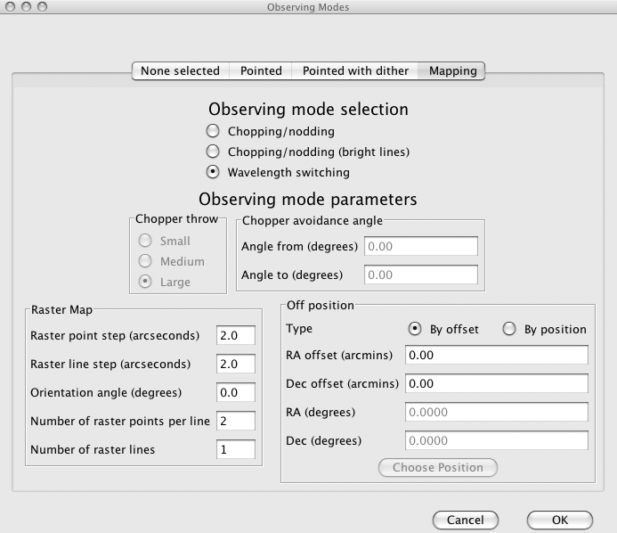
Setting up the instrument mode parameters on the "Mapping" screen is identical to that for the "Pointed" or "Pointed with dither" modes. The one difference can be seen at the bottom of the tab within the "Raster map" frame.
This mode allows the observer to set up a raster map observation in combination with chopping/nodding or wavelength switching techniques. The chopping/nodding layout is identical to the logic applied for "Pointed" and "Pointed with Dither" modes, however, nodding cycles are repeated for every raster positions. The wavelength switching option is described below.
The figure above (Figure 11.7, “ Options for the Mapping observing mode”) shows the user options for raster mapping, however, parameter validation and ranges are slightly different depending on whether chopping/nodding, or wavelength switching is selected.
The centre of the map is at the coordinates given by the target position. The map size along a raster line can be expressed as the number of raster points per line times the raster point step. In perpendicular direction, the map size is given by the number of raster lines times the raster line step. Mapping parameter ranges are defined as:
Raster point step in [2, 480] arcseconds
Raster line step in [2, 480] arcseconds
Number of raster points per line in [2, 100]
Number of raster lines in [1, 100]
![[Note]](../../admonitions/note.gif) | Note |
|---|---|
|
Selecting the chop/nod mode the map (raster line) orientation is defined by the chopping direction, the observer has no direct access to the map orientation parameter (disabled field). However, the observer has two choices to influence the map orientation:
by setting a timing constraint or
by setting a chopper avoidance angle (see the restrictions in Section 10.5, “Position angle and chopper avoidance”)
In wavelength switching mode the map orientation can be set via the "Orientation angle" parameter. The telescope moves along raster lines in a direction with a position angle between 0 and 360 degrees from North to East in equatorial coordinate system.
If by chopping a maximum of six arcminutes the field-of-view would not be placed in an emission-free area, the observer should consider wavelength switching as an alternative of the chopping mode. There may be be other reasons in a number of science cases to use this option. For very bright objects chopping to off-source could introduce a high contrast, resulting in memory effects in the spectrometer's Ge:Ga detectors. Such an effect would lead to data that can only be poorly calibrated.
In wavelength switching mode PACS is "chopping" in the spectral domain using a small grating throw. The grating is frequently switched between two positions symmetrically placed with respect the central wavelength of the instantaneous coverage. The symmetry centre of the grating pattern corresponds to the line central wavelength you specified in the PACS Line Editor table. In this mode the spectral line is kept always on-array, however, due to the limited wavelength span of the instantaneous coverage and with the aim for a better spectral sampling a number of dithering cycles are applied with a slightly shifted central wavelength (i.e. dithering in the spectral domain). In case the number of switching cycles is specified larger than one then the entire dithering/switching pattern is repeated on every raster positions. Wavelength switching can be done only in combination with an off-position measurement. Moving to the observer specified off-position PACS repeates the same wavelength switching observing block as for every raster positions. Such an off-position is visited before beginning- and after finishing the raster pattern. The rational behind the mandatory off-position is related to the fact that even for small grating throws one could notice a relatively large contrast in the relative spectral response function of the PACS spectrometer. In case the grating switches between two positions of a noticable response difference then one might introduce artefacts in the data due to unwanted detector memory effects. Data obtained in the off-position helps to eliminate this effect. There is no observing parameter the user can access for this mode. You can select wavelength switching by clicking on the "Wavelength switching" option button in the "Observing mode selection" field.
![[Note]](../../admonitions/note.gif) | Note |
|---|---|
| The continuum information is eliminated when using wavelength switching technique. This mode is very inefficient if significant continuum gradients are expected over the covered wavelength range. More information about this mode can be obtained in the PACS Observers' Manual (http://herschel.esac.esa.int/Docs/PACS/html/pacs_om.html). |
![[Note]](../../admonitions/note.gif) | Note |
|---|---|
| In case of bright embedded point- or compact source observations it is highly recommended to specify a 2x1 raster with step size as small as half a spatial pixel (4.5 arcseconds) respectively. This setup ensures a good spatial sampling and dithering for the shortest duration wavelength-switching observations. |
The off-position can be specified by relative offset in arcminutes with respect the target coordinate, or alternatively, you can define an absolute position within a two degrees radius. In case you prefer to use the absolute position option then it is highly recommended to specify RA/Dec via the standard HSpot target definition window. You can have access to this window by clicking on the "Choose Position" button.
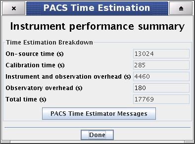
To get a time estimate for the observing mode configuration chosen and its associated noise level, click the "Observation Estimation" button on the bottom of the AOT main screen. This runs the PACS Time Estimator and once the calculation is done brings up a window "PACS Time Estimation".
Running the estimator invokes a sequence of optimisation processes through possible combinations stored in instrument configuration tables. This process selects the most efficient way of observing on-target, reference and calibration measurements and also minimises the instrument overheads.
The exact time for the observing sequence and the associated expected noise are presented to the observer. A set of messages and information regarding the sequence chosen are also given.
The breakdown of the observation is provided in the "PACS Time Estimation" screen (Figure 11.8, “ PACS Time Estimator main window”). It indicates the on-source time, calibration time, instrument and observatory overheads and the total observing time. Further details on calculation of the timing components can be obtained in the PACS Time Estimator messages window (see below).
![[Note]](../../admonitions/note.gif) | Note |
|---|---|
| The 180 seconds observatory overhead is always charged to the observer as a compensation for the initial slewing time. In case the AOR is constrained (see Section 10.5, “Position angle and chopper avoidance” and Chapter 16, Timing Constraints Editing ) a total of 10 minutes observatory overhead is charged. |
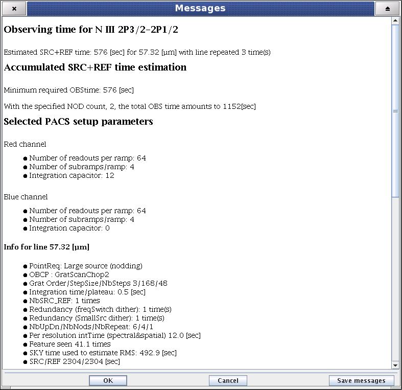
More detailed information can be obtained by clicking the "Messages" button on the "PACS Time Estimation" screen.
The message window presents information of two kinds: (1) a summary of the data entered in HSpot (line wavelengths and observing mode parameters); and (2) several relevant pieces of timing information, as well as the RMS noise and signal-to-noise for the resulting times:
HSpot decoding logic; number of repetitions per spectral line and observing time per line per pointing position
Observing time required; minimum observing time and actual requested time
AOT, pointing mode and nodding / wavelength switching info
Global AOT durations
Setup and calibration summary
Spectral line summary; observing wavelengths, continuum sensitivity for a point source, spectral line sensitivity for a point source, observing time spent per line, on-source time plus observing time on reference position (chop-off field)
