As seen in Figure 2.11, “The HIFI signal chain.”, the HIFI Signal Chain includes the 14 Mixer Units, the First- and Second-Stage Amplifiers (in the FPU), the Upconverter and 3-dB Coupler (which are located in the satellite's service module), and the Isolators that are used to suppress reflections between the Mixer Units and the First-Stage Amplifiers.
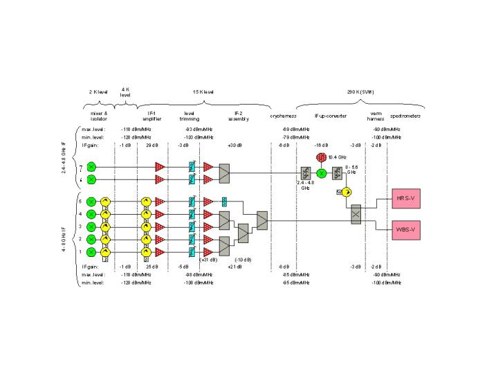
In Bands 1 to 5, each Signal Chain consists of a mixer, followed by two isolators, and two amplifiers. For each polarization, the outputs of these 5 independent chains are combined, so that only two cables are needed to carry the IF outputs from these 10 channels of the FPU to the service module.
The situation in Bands 6 and 7 is similar, except that isolators are not used (because they are not available for the 2.4-4.8 GHz IF band that is needed for the HEB mixers). Thus, the second pair of IF output cables from the FPU includes the combined outputs of the two polarizations of Band 6 and 7. The other difference in the Band 6/7 Signal Chain is that an IF Up-converter is needed to transform the 2.4-4.8 GHz output of the FPU to 8-5.6 GHz, for compatibility with the spectrometers.
Within the "IF Up-converter" (in the service module), a 3-dB Coupler is also used to combine the Bands 1-5 and 6-7 outputs, so that each "polarization" of the Wide-Band and High-Resolution Spectrometers is connected to all 7 bands by a single input cable (although a signal is only received from the active band).