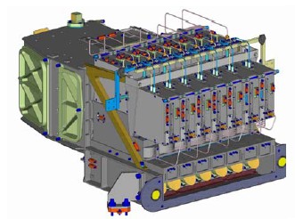
The HIFI Focal Plane Sub-System consists of three hardware units: the Focal Plane Unit (FPU, see [1]), which is located on the optical bench in the Herschel cryostat and depicted in Figure 2.4, “HIFI Focal Plane Unit (FPU).” and Figure 2.5, “Back side of the HIFI FPU.”; the Up-converter and 3-dB Coupler (described in Section 2.4, “The HIFI Signal Chain”) are contained in the satellite's service module -- see the Observatory handbook for details on the service module; and the Focal Plane Control Unit (FCU), also contained in the satellite's service module). Additionally, the critical signal chain elements that together define the instrument's sensitivity (the mixers, isolators in bands 1 to 5, and amplifiers, plus the IF up-converter used in Bands 6 and 7) together form the HIFI Signal Chain.
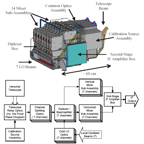
In practice, the HIFI signal chain is a virtual unit, since its elements are physically distributed throughout the FPU. The complexity of the FPU has necessitated a modular design in which the Focal Plane Unit is divided into six major assemblies: the Common Optics Assembly; the Diplexer (beam combiner) Assembly; the Mixer Sub-Assemblies (of which there are 14); the second-stage IF amplifier box; the Focal Plane Chopper; and the Calibration Source Assembly (see Figure 2.4, “HIFI Focal Plane Unit (FPU).”).
The Common Optics Assembly, forms the basis of the FPU structure, and mounts directly on the Herschel optical bench.
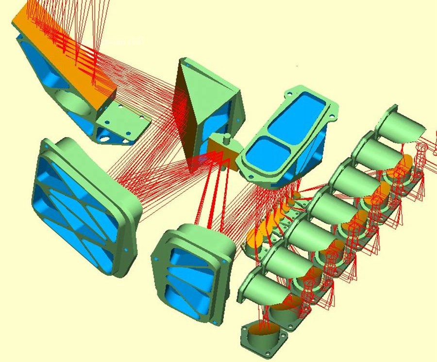
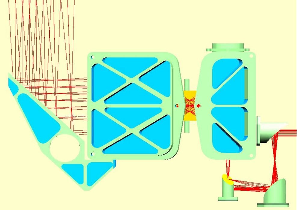
Figure 2.7. The channel splitting optics -- as seen from the side with respect to Figure 2.6, “HIFI telescope relay optics.”.
The optics assembly relay the instrument's 7 signal beams from the telescope's focal plane into a diplexer box. This is done with 6 common mirrors (the telescope relay optics, see Figure 2.6, “HIFI telescope relay optics.”) and 7 sets of 3 mirrors (the channel-splitting optics, see Figure 2.7, “Channel splitting optics”). Together, these optics have three primary functions:
They produce an image of the telescope secondary on the fourth mirror in the chain after the secondary (M6), enabling the implementation of a Focal Plane Chopper.
They produce an image of the telescope focal plane on the first mirrors in the Channel-Splitting Optics, allowing the beams to be split by seven mirrors with different orientations.
In each channel, they create an image of the telescope secondary within the beam combiner assembly (see Section 2.3.2, “ The Beam Combiner Assembly (Diplexer Unit)”). This image has a large Gaussian beam waist, to minimize diffraction losses, and a frequency independent size, to simplify visible-light alignment.
The seven local oscillator beams from the Local Oscillator Unit enter the FPU through windows in the cryostat. Using 7 sets of five mirrors, the Cold Local Oscillator Optics re-image the LO beam waists at the FPU input to waists in the diplexer box that match those produced by the channel-splitting optics.
Within the beam combining assembly, each of the 7 signal beams is combined with its corresponding local oscillator beam, creating two linearly polarized beams per channel (referred to as Horizontal, H, and Vertical, V, beams). Each of these 14 beams is then directed into a Mixer Sub-Assembly.
At low frequencies, where significant LO powers are available, the combining is done with polarizing beamsplitters. As seen in Figure 2.8, “ Beamsplitter and diplexer mixing with sample diplexer unit.”, one beamsplitter is placed at the intersection of the LO and signal beams, creating two mixed beams (one contains the horizontally polarized signal beam and the vertically polarized LO beam, while the second contains the inverse). Each of the mixed beams then hits a second beamsplitter, which is oriented to reflect 90% of the signal power and 10% of the LO power (the remaining power is absorbed in a beam-dump).
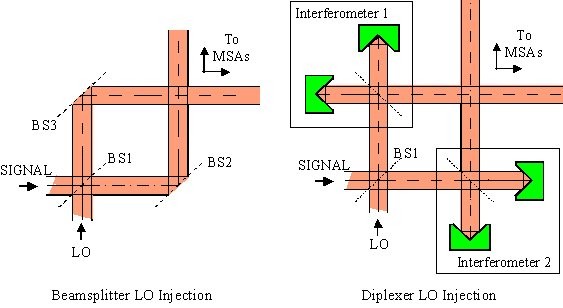
At high frequencies, where LO power is scarcer, a Martin-Puplett diplexer is used for LO injection (see Figure 2.8, “ Beamsplitter and diplexer mixing with sample diplexer unit.”). As in the beamsplitter channels, the first beamsplitter creates two beams containing LO and signal power in orthogonal polarizations. However, in this case, the second beamsplitter is replaced with a polarizing Michelson interferometer that rotates the LO beam polarization relative to that of the signal beam, creating a linearly polarized output. In this manner, the coupling of both the LO and signal powers to the mixers is high (95%, or better), although diplexer scanning mechanisms are needed for frequency tuning.
The mixers at the heart of the Focal Plane Unit largely determine the instrument's sensitivity. For this reason, the mixer technologies used in each band have been selected to yield the best possible sensitivity. In particular, a range of Superconductor-Insulator-Superconductor (SIS) mixer technologies are being used in the lowest 5 frequency bands (covering 480-1250 GHz; see Refs [2], [3], [4] and [5]), while the top two bands (covering 1410-1910 GHz; see Refs [6], and [7]) incorporate Hot Electron Bolometer mixers (HEB mixers).
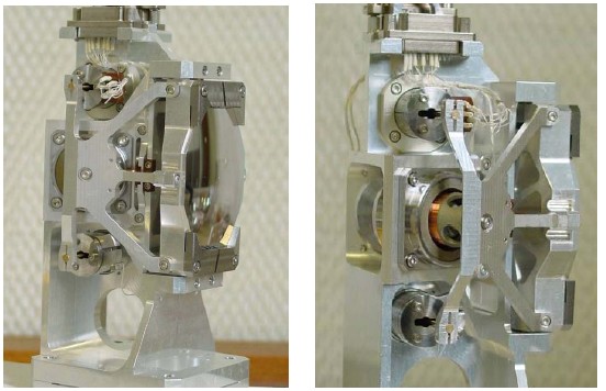
Each of the 14 linearly polarized outputs from the diplexer/beam combiner box enters a Mixer Sub-Assembly (MSA -- see Figure 2.9, “ A HIFI mixer sub-assembly.”) that includes:
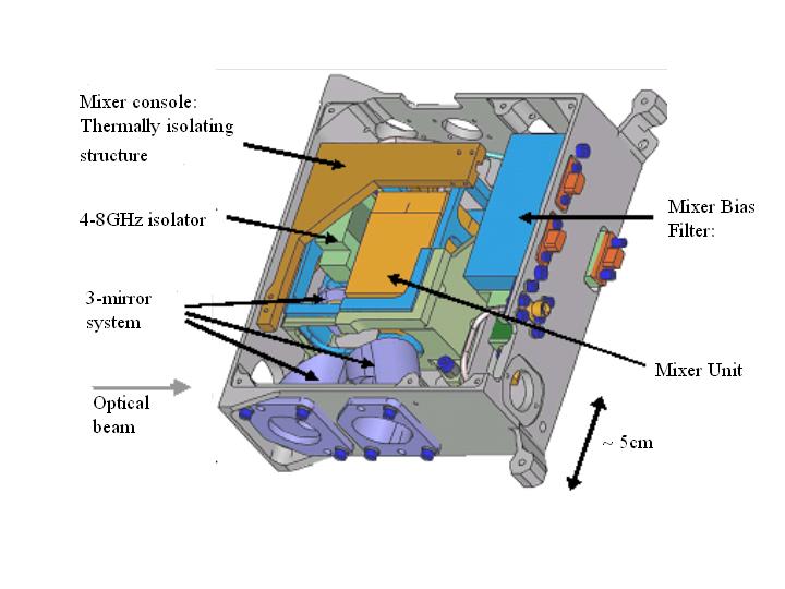
a set of three mirrors that focus the optical beam into the mixer;
a mixer unit where the incoming signal and LO signal are combined;
a low-noise IF amplifier (plus two IF isolators - for bands 1 to 5 - that suppress reflections in the cable between the mixer and the amplifier);
low-frequency filtering for the mixers DC bias lines; and
a mechanical structure that thermally isolates the mixer unit (at 2 K) from the FPU structure (at 10 K).
The Focal Plane Chopper (FPC) is the sixth mirror of the telescope relay optics (M6, see Figure 2.10, “The HIFI Focal Plane Chopper (FPC).”). The chopper mirror is able to rotate (in one direction) around the centre of its optical surface. Tilting the chopper is equivalent to tilting the telescope secondary, which moves the beam on the sky. The primary uses of the chopper are to steer the beam on the sky, and to redirect the instrument's optical beam into the on-board calibration sources.
The beam switch on the sky is currently a fixed parameter for the user. The beam switch being 3' on the sky. There are two chopper speed regimes available to the user, a "fast" chop (up to 4Hz depending on the goal resolution, being faster for larger resolutions) and a "slow" chop (typically 0.125Hz if all 4 spectrometers are used simultaneously, but twice as fast if two backends are switched off -- e.g., WBS only). The FPC is designed to have a settling time under 20msecs.
Mounted on the side of the Common Optics Assembly, the Calibration Source Assembly includes two blackbody signal loads that are used to calibrate the instrument's sensitivity (the first is an absorber at the FPU temperature around 10K, while the second is a lightweight blackbody cavity that can be heated to 100K), plus mirrors that focus the FPU's optical beam into the loads. Temperature sensors are available to read out the actual temperature of both calibration loads. The HIFI optical beam is steered towards the calibration sources by the use of extreme positions of the Focal Plane Chopper.