This section summarises the main characteristics of the Herschel spacecraft, its orbit, pointing performance and observable sky regions.
The Herschel spacecraft has a modular design, comprising of the Extended Payload Module (EPLM) and the Service Module (SVM) The EPLM consists of the PLM "proper" with a superfluid helium cryostat - based on the proven ISO technology - housing the Herschel optical bench (HOB) with the instrument focal plane units (FPUs), and supporting the telescope, the sunshield/shade, and payload associated equipment. The SVM houses "warm" payload electronics and provides the necessary "infrastructure" for the satellite such as power, attitude and orbit control, the onboard data handling and command execution, communications, and safety. Figure 1 shows the main components of the Herschel S/C. Table 1 presents the Herschel Spacecraft key characteristics.
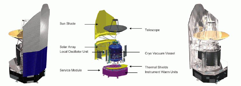
Figure 1. The Herschel spacecraft has a modular design. On the left, facing the "warm" side and on the right, facing the "cold" side of the spacecraft, the middle image names the major components.
Table 1. Herschel Spacecraft key characteristics
| S/C Type: | Three-axis stabilised |
| Operation: | Autonomous (3 hours daily ground contact period) |
| Dimensions: | 7.5 m high x 4.0 m diameter |
| Telescope diameter: | 3.5 m |
| Total mass: | 3170 kg |
| Solar array power: | 1500 W |
| Average data rate to instruments: | 130 kbps |
| Absolute pointing Error (APE): | 2.45 arcsec (pointing) / 2.54 arcsec (scanning) |
| Relative Pointing Error (RPE, pointing stability): | 0.24 arcsec (pointing) / 0.88 arcsec (scanning) |
| Spatial Relative Pointing Error (SRPE): | 2.44 arcsec |
| Cryogenic lifetime from launch: | min. 3.5 years |
So that the favourable conditions offered by being in space can be exploited to the full, Herschel will carry a precise, stable, low background telescope. The Herschel telescope will be passively cooled to maximise its size, which is only limited by the size of the fairing on the Ariane 5-ECA rocket. The Herschel telescope must have a total wavefront error (WFE) of less than 6 μm (corresponding to "diffraction-limited" operation at < 90 μm) during operations. It must also have a low emissivity to minimize the background signal, and the whole optical chain must be optimised for a high degree of straylight rejection. In space the telescope will cool radiatively, protected by a fixed sunshade, to an operational temperature in the vicinity of 80 K, with a uniform and very slowly changing temperature distribution.
The chosen optical design is a classical Cassegrain with a 3.5-m diameter primary and an "undersized" secondary. The telescope has been constructed almost entirely of silicon carbide (SiC). The primary mirror (M1) has been made out of 12 segments that have been brazed together to form a monolithic mirror, which was machined and polished to the required thickness (~3-mm) and accuracy. The secondary mirror (M2), with 308-mm diameter, has been manufactured in a single SiC piece. It is adjusted on the SiC barrel by tilt and focus adjustment shims. In order to avoid the Narcissus effect on the detectors, the central part of the secondary mirror is shaped in such a way that no parasitic reflected beam can enter the focal plane.
The hexapod structure (also made of SiC) supports M2 in a stable position with respect to M1. Finally, three quasi-isostatic bipods, made of titanium, support the primary mirror and interface with the cryostat. The focus is approximately one metre below the vertex of M1, inside the cryostat.
The proper telescope alignment and optical performance have been measured on ground in cold conditions. The measured wavefront performance in cold is in line with the requirements. The measured position has been found reproducible on a number of cooldown cycles and can be accommodated at spacecraft alignment level by adjusting the shimming. However, there is no possibility of in-flight adjustments such as focusing (this was also the case for ISO).
The M1 and M2 optical surfaces have been coated with a reflective aluminium layer, covered by a thin protective "plasil" (silicon oxide) coating. The telescope will initially be kept warm after launch into space to prevent it acting as a cold trap while the rest of the spacecraft is cooling down.
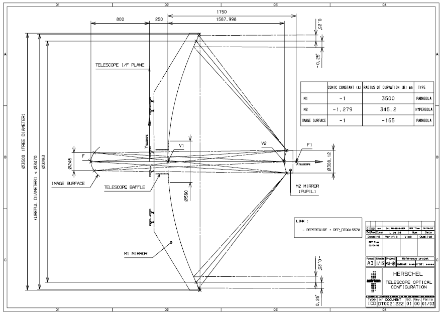
Key telescope data are summarised in Table 2. A diagram is shown in Figure 2
Table 2. The Herschel Telescope's predicted characteristics at working temperature (70 K)
| Configuration: | Cassegrain telescope |
| M1 Free diameter: | 3500-mm |
| Focal length: | 28500-mm |
| f-number: | 8.68 |
| Field of View radius: | 0.25° |
| M1 curvature radius / conic constant: | 3499.02-mm / -1 |
| Aperture stop / distance to M1 apex: | M2 mirror / 1587.555-mm |
| M2 diameter: | 308.11-mm |
| M2 curvature radius / conic constant: | 345.2-mm / -1.279 |
| Image diameter: | 246-mm |
| Image curvature radius / conic constant: | -165-mm / -1 |
| On-axis best focus distance to M1 vertex: | 1050-mm |
The Herschel cryostat houses the focal plane units of the three scientific instruments depicted in Figure 3. The cooling concept for the Herschel instruments is based on the proven principle used for the ISO mission. The temperature required in the instrument focal plane is provided down to 1.7K by a large superfluid helium Dewar (helium at 1.6K), sized for a scientific mission of 3.5 years. This is achieved with a total amount of 2160 litres of helium cryogen. The cryostat provides 1.7K as its lowest service temperature to the instruments. Further cooling down to 0.3K, required for two instruments (the SPIRE and PACS bolometers) is achieved by dedicated 3He sorption coolers that are part of the respective instrument focal plane unit. In orbit the liquid Helium is maintained inside the main tank by means of a phase separator (a sintered steel plug). The heat load on the tank will evaporate the Helium over the mission time at an estimated rate of about 200 grams per day. The enthalpy of the gas is used efficiently to cool parts of the instruments that do not require the low temperature of the tank (two temperature levels, at around 4K and around 10K). After leaving the instruments the evaporated gas is further used to cool the 3 thermal shields of the cryostat.
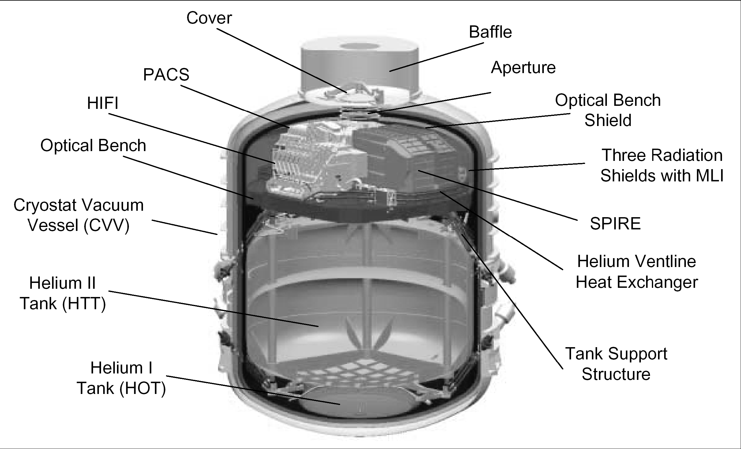
During ground operations, the vacuum vessel is closed by the means of a cover, located at its top, which is opened once in orbit. To maintain a cold environment inside the cryostat during the last few days before launch in Kourou, an auxiliary liquid Helium tank is used. The space side of the Cryostat Vacuum Vessel (CVV) is used as a radiator area to cool the CVV on orbit to a final equilibrium temperature of about 70K. This radiator area is coated with high emissive coating to achieve low temperatures in the L2 orbit. Multi-Layer-Insulation (MLI) covers the outer CVV-surfaces, in order to insulate it from the warm items (satellite bus and Sunshield). The outer layer of the MLI is optimised for the lowest temperature of the CVV. The outside of the cryostat is the mechanical and thermal mounting base for the Herschel telescope, the Local oscillator unit of HIFI, the Bolometer Amplifier Unit of PACS and the large sunshield protecting the CVV from the sun.
The science payload is accommodated both in the "cold" (CVV) and "warm" (SVM) parts of the satellite. The instrument FPUs are located in the "cold" part, inside the CVV mounted on the optical bench, which is sitting on top of the superfluid helium tank. They are provided with a range of interface temperatures from about 1.7 K by a direct connection to the liquid superfluid helium, and additionally to approximately 4 K and 10 K by connections to the helium gas produced by the boil-off of liquid helium gas, which is used efficiently to provide the thermal environment necessary for their proper functioning. The "warm" - mainly electronics - parts of the instruments are located in the SVM. The following instruments are provided within the Herschel spacecraft:
The Photodetector Array Camera and Spectrometer (PACS)
The Spectral and Photometric Imaging REceiver (SPIRE)
The Heterodyne Instrument for the Far Infrared (HIFI)
The instruments are described in their respective users' manuals
The service module (SVM) is the box-type enclosure at the bottom of the satellite, below the EPLM and carries all spacecraft electronics and those instrument units that operate in an ambient temperature environment. It is depicted in Figure 4.
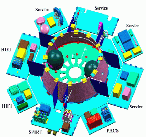
SVM modularity is achieved by implementing units of similar function on each of the panels. Panels are either dedicated to one instrument or to a single sub-system (Attitude Control, Power, Data handling-telecommunications). The propellant tanks are symmetrically implemented inside the central cone. The SVM also ensures the mechanical link between the launcher adapter and the EPLM.
The electrical power of the satellite is produced by the solar array. The solar array is in front of the cryostat to protect it from solar radiation. The rear of the sunshield is covered with multi layer insulation as is the part of the cryostat facing this warm part of the system. The geometrical design has to consider the size of the cryostat and the telescope, the required sun aspect angles of the s/c in orbit and the limited diameter of the fairing of the launcher. For Herschel a relatively simple system with a fixed solar array has been selected. The lower part actually carries the solar cells. The upper part is free of solar cells to allow it to be at a lower temperature, which in turn helps for the telescope to stay at the required temperature. The height of the sunshield is driven by the need to shade the entire telescope when the spacecraft is pointed closest to the sun (60° Sun aspect angle).
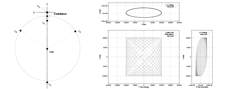
Figure 5. Left: Position of the Lagrange points for the Sun-Earth/Moon system. L2 lies 1.5 million kilometres from Earth. Right: An example of a Lissajous orbit around L2. The X and Y-axis are as shown in the plot on the left, the Z-axis is normal to paper.
The Herschel spacecraft will be eventually placed in a large "halo"[1] orbit around L2, with an amplitude of about 700000-km and a period of ≈ 178 days. The distance from the Earth ranges from 1.2 to 1.8 million km. Planck requires a smaller orbit around L2, with a maximum Sun-S/C-Earth angle of around 15° (driven by telecommunication link and instrument straylight requirements) and will therefore perform a major insertion manoeuvre three months after launch.
The orbit chosen for Herschel presents a number of advantages summarised below:
Simplifies long observations, since the Sun and the Earth remain close to each other as seen by the S/C (Sun-S/C-Earth angle always < 40°)
Very stable thermal and radiation environment
No trace of atmosphere
A large halo orbit can be achieved without any injection Δv
Major drawbacks are the long distance for communications and the fact that orbits around the L2 are unstable; without orbit corrections the spacecraft would deviate exponentially from the nominal one. Small correction manoeuvres, applied at monthly intervals will maintain the orbit close to the nominal one. Figure 4 shows a example of large halo orbit for Herschel (from [RD2])

Figure 6. A 3D representation of the Herschel orbit for a hypothetical launch on 15th November 2007. The Earth is located at (0,0,0)
The operations of Herschel and Planck spacecrafts will be performed by the European Space Operation Centre (ESOC) in Darmstadt (Germany). The ground station will be located in Perth (Australia) where a 35-metre antenna using X band up and down links will be used. The ground station communication link will be limited to a duration down to 3 hours per day for each Herschel and Planck spacecraft. Therefore, it is required:
Large on-board data storage (around 40Gbit)
High TM rate (around 1.5Mbps)
High spacecraft operational autonomy between two visibility periods.
The areas of the sky accessible to the Herschel telescope are determined by a number of constraints applicable to Sun, Earth, Moon and other bright solar system objects. In particular, the following constraints are applicable through the mission:
Sun-S/C-Earth angle of 37°
Sun-S/C-Moon angle of 47°
Sun-S/C-LoS angle of 60° to 120° (in the S/C XZ plane)
Maximum roll angle of ±1°
In addition, the nominal half-cone exclusion angles listed in Table 3 apply to observations towards major planets.
Table 3. Nominal exclusion angles (half-cones) for observation towards major planets
| Instrument | Mode | Mars | Jupiter | Saturn | Instrument |
|---|---|---|---|---|---|
| Critical | |||||
| a. SPIRE has determined that, while Jupiter and possibly Saturn will not damage the instrument, they would render it inoperable for a significant period (possibly even an entire OD) | |||||
| b. HIFI wishes to avoid straylight pollution when observing fainter objects with a SSO close to the instrument LoS. The instrument will not be harmed by the presence of a major SSO in the FoV and will, in fact, even use Mars as its primary calibrator. | |||||
| c. During slews, the detectors are ON (photometry, spectroscopy or parallel mode). | |||||
| d. During non-SSO PACS observations. PACS may well wish to observe these SSOs directly. | |||||
| SPIRE | Slew | None | 15 arcmin | 15 arcmin | Yesa |
| Pointing | None | 15 arcmin | 15 arcmin | Yesa | |
| HIFI | Slew | None | None | None | Nob |
| Pointing | 36 arcmin | 36 arcmin | 36 arcmin | No | |
| PACS | Slew | 4 arcmin | 4 arcmin | 4 arcmin | No |
| Pointing | 1.5 deg | 1.5 deg | 1.5 deg | No | |
The sky visibility for each date depends on the orbit and the launch date. Figure 7 shows the sky visibility throughout the mission and computed for two particular launch dates.


This section deals with the pointing performance of the Herschel spacecraft. The spacecraft Attitude Control and Measurement System (ACMS) consists of several components, as depicted in Figure 8. The main constituents of the ACMS are the attitude control computer (ACC), gyroscopes (GYR), star trackers (STR), reaction control system (RCS), reaction wheel assembly (RWA), Sun acquisition sensors (SAS), coarse rate sensors (CRS) and attitude anomaly detectors (AAS).
In normal Science Mode (SCM), the spacecraft attitude is computed by combining the STR and GYR measurements in the ACC using a linear Kalman filter. The so-called "filtered attitude" is sampled and downloaded with a frequency of 4Hz.

The following pointing accuracy definitions apply to the Herschel spacecraft:
Absolute Pointing Error (APE): the angular separation between the desired direction and the actual instantaneous direction.
Absolute Measurement Error (AME): the angular separation between the actual and the estimated pointing direction (a posteriori knowledge).
Pointing Drift Error (PDE): the angular separation between the average pointing direction over some interval and a similar average at a later time.
Relative Pointing error (RPE) or pointing stability: the angular separation between the instantaneous pointing direction and the short-time average pointing direction at a given time period (in this case 60 sec).
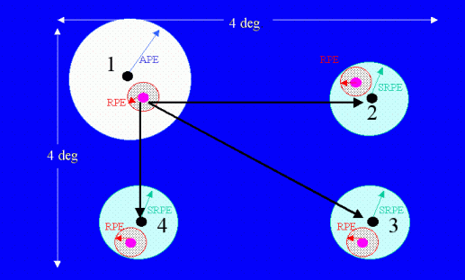
Spatial Relative Pointing Error (SRPE): angular separation between the average orientation of the satellite fixed axis and a pointing reference axis, which is defined to an initial reference direction. See Figure 9 (from I. Rassmusen).
The main error contributors are:
To AME and APE:
Position-dependent bias within STR. It is also the main contributor to SRPE.
Residuals from calibration
Thermo-elastic stability of the structural path between STR and FPU
Instrument LoS calibration accuracy w.r.t. ACA frame (best for PACS)
To PDE: Thermo-elastic stability
To RPE: The main contributor is the noise in the control loop comprising STR+Gyro noise attenuated by a linear Kalman filtering.
Table 4 summarises the pointing performance of the Herschel spacecraft. The most outstanding non-compliance is related to the SRPE (required 1 arscec vs. predicted performance 2.44 arcsec).
Table 4. Herschel pointing requirements SRS 3.2
| LoS (arcsec) | Around LoS (arcsec) | LoS Goals | ||||
|---|---|---|---|---|---|---|
| Notes | ||||||
| a) Interlacing, also at calibration, thermal goal: STR, SVM, HPLM. | ||||||
| b) STR interlacing. | ||||||
| c) STR interlacing and STR thermal goal conditions. | ||||||
| Name | Req | Performance | Req | Performance | Performance | Notes |
| APE point | 3.7 | 2.45 | 180.00 | 44.47 | n.a | |
| APE point Goal | 1.5 | n.a | n.a | n.a | 1.45 | a) |
| APE scan | 3.7 | 2.54 | n.a | n.a | n.a | |
| APE scan Goal | 1.5 | n.a | n.a | n.a | 1.63 | a) |
| PDE (24 hours) | 1.2 | 0.71 | 180.00 | 8.66 | n.a. | |
| RPE point (60 sec) | 0.3 | 0.24 | 90.00 | 1.68 | n.a | |
| RPE Scan (60 sec) | 1.2 | 0.88 | 90.00 | 7.69 | n.a | |
| RPE scan Goal (60 sec) | 0.8 | n.a | n.a | n.a | 0.81 | b) |
| AME Point | 3.10 | 2.40 | 180.00 | 38.15 | n.a | |
| AME Point Goal | 1.20 | n.a | n.a | n.a | 1.42 | a) |
| AME Scan | 3.10 | 2.52 | 180.00 | 43.32 | n.a | |
| AME Scan Goal | 1.20 | n.a | n.a | n.a | 1.62 | a) |
| AME Slew | 10.00 | 2.59 | 180.00 | 43.27 | n.a | |
| AME Slew Goal | 5.00 | n.a | n.a | n.a | 1.80 | a) |
| SRPE | 1.00 | 2.44 | n.a | n.a | n.a | |
| SRPE c) | 1.00 | n.a | n.a | n.a | 1.52 | c) |
The main characteristics of Herschel STR are:
The ability to determine the inertial position from "lost in space"
FoV: 16.4 × 16.4 deg²
An onboard catalogue, based on Hipparcos, some 3000-3500 stars contained
A minimum of 3 stars, 9 is the maximum due to HW limitations.
The STR bias is the largest contributor to APE and is pixel-dependent (some 0.8" × √2)
Enhanced performance mode: "interlaced mode", only applicable if ≥ 18 stars in FoV. The STR samples at twice the nominal frequency (4 Hz), 9 stars at a time. A low scan rate (0.2 arcsec/sec) is required. The use of both STRs simultaneously is being considered; this would yield an improved AME.
The STRs provide an absolute reference, but are not accurate enough. In particular, they are responsible for the SRPE non-compliance. On the other hand, gyroscopes are very accurate, but only on short temporal (bias drift, 0.0016 deg/hour) and spatial (scale factor stability, above 4 deg) scales. Therefore, the gyro attitude must be recalibrated using the STR information. A mechanism has been devised to perform raster pointings using exclusively the accurate gyro information. This is called the "gyro propagation mode" (a.k.a. Calibration Pointing or CP). The procedure consists of the following steps:
Initial fixed pointing of 30 min to calibrate the gyro bias
Within the next two hours:
Initial 15 sec calibration in the OFF position
600 sec between the recalibrations of the gyros
15 sec recalibration in the OFF position.
This mode has been implemented only for raster pointings.