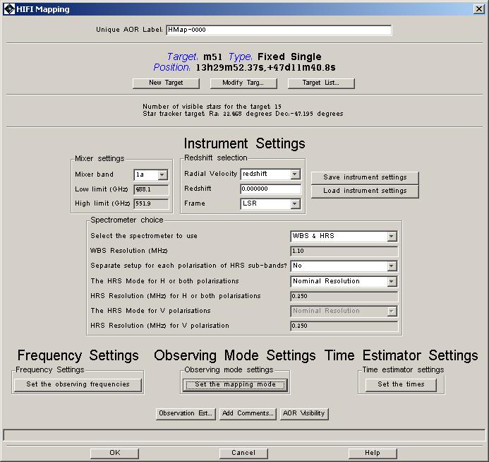
The AOT screen for the "HIFI Mapping" AOT is very similar to that for the pointed observation mode (see Figure 13.19, “ HIFI Mapping AOT window”). Essentially, setting up the instrument is identical for each of the pointed and mapping modes, including the setting up of the time estimator. The one difference can be seen at the bottom of the AOT screen under "Observing Mode Settings". Clicking the button marked "Set the mapping mode" allows the choice between "On-the-Fly" and "DBS raster" mapping (see Figure 13.20, “ HIFI mapping mode choice window”).
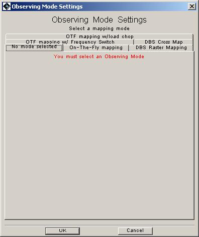
To choose the mapping mode that you want, just click on the appropriate tab.
"On-the-Fly" mapping involves continuous readout while scanning and is potentially a very efficient mode. This mode can also be used with a frequency switch option. Dual Beam Switch (DBS) raster and cross maps involve using the DBS pointed mode -- with 3 arcminute chop throws -- at each map point (see Figure 13.20, “ HIFI mapping mode choice window”).
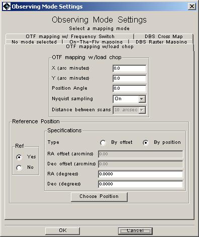
In Figure 13.21, “ HIFI On-The-Fly map with position switch setup window.” the options for the position switch version of the OTF mapping modes are displayed. The X direction = in-scan direction while the Y direction = cross-scan direction. The in-scan and cross-scan sampling has the same spatial size, typically Nyquist sampling.
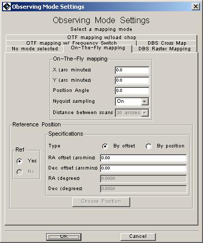
The centre of the map is at the coordinates given by the target position. The total in-scan and cross-scan lengths (in arcminutes) then indicate the size of the map around this centre. The total in-scan length is restricted to 90 arcminutes or less. However, for higher frequency measurements, where calibrations are more frequently required, the scan length is restricted to much less than this.
![[Warning]](../../admonitions/warning.gif) | Warning |
|---|---|
The length of a scan in the X direction is limited by the maximum length of time that can be taken between load calibrations. Since the high frequency bands have shorter stability times, this effectively restricts map sizes to only a few arcminutes in bands 6 and 7 (approx. 10-12 arcminutes for Nyquist sampling in bands 6 and 7, with all spectrometers in use). An increased map size in a single AOR can be obtained by
|
Restrictions on the cross-scan size (Y direction) come only from the total time allowed for a single observation.
In order to do an OTF map, the telescope is scanned in a direction with a position angle between 0 and 360 degrees from north to east.
The user can either have Nyquist sampling (the default), or can choose to have a cross-step. Choosing Nyquist sampling or not is given by a "Yes/No" pull-down menu (see Section 13.3.1, “On-the-Fly (OTF) Mapping setup”). If "No" is chosen the user has a selection of available cross-step values (in arcseconds) that can be used.
The OTF mapping mode with position switch requires a reference OFF position to be used. This can be incorporated in the same way as the pointed mode reference positions (e.g., see the section called “Identifying a reference position”).
![[Note]](../../admonitions/note.gif) | Note |
|---|---|
| The reference position MUST be within 2 degrees of the target. |
This mapping mode has the same elements as the OTF scanning (see Section 13.3.1, “On-the-Fly (OTF) Mapping setup”) but allows the user to additionally use a frequency switch while scanning. There is therefore the additional user input parameter of the frequency throw for the frequency switch. This mode does not require the user to use a reference OFF position. Referencing only occurs between the frequency-switched positions or source-load positions in the frequency switch and load chop cases respectively. However, accurate bandpass measurements allowing for best continuum baseline removal should use a frequency switch measurement of an OFF position too, and this is highly recommended.
This mode is particularly useful for situations where the stability times are short (such as in the cases of bands 6 and 7) and where standard OTF maps use a reference at the ends of line scans which may take long periods of time leading to large drifts in the system response. However, OTF with load chop should be preferred for cases where there is a complex spectrum due to spectral line density or the existence of broad lines (several tens of km/s).
The mode requires the same input parameters as the standard OTF mapping mode (see Section 13.3.1, “On-the-Fly (OTF) Mapping setup”) except for the fact that an OFF position is optional (see the section called “Identifying a reference position” for information) and that a frequency throw needs to be selected by the user (see Figure 13.22, “ HIFI On-The-Fly map with frequency switch setup window.”).
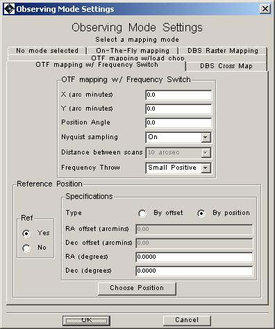
For the frequency throw the user uses a pull-down menu of available frequency throws (see Section 13.2.7.3, “Frequency Switch mode”). Currently there are 4 values allowed, of "small positive", "large positive", "small negative" and "large negative". Where "small" and "large" are of order 100 and 200-300 MHz respectively (see Table 13.1, “Frequency throw values available by HIFI subband.” for details).
This mapping mode has the same elements as the OTF scanning (see Section 13.3.1, “On-the-Fly (OTF) Mapping setup”) but allows the user to additionally use a load chop referencing scheme while scanning (see Section 13.2.7.4, “Load Chop mode”). The mode does not require the user to use a reference OFF position. Referencing only occurs between the sky position and the internal cold load. However, by doing this, the signal path towards the ON and the OFF become imbalanced and standing waves are not so efficiently removed. Note that the magnitude of this imbalance is yet unknown since measurements performed with the telescope secundary will only be available once in orbit. Accurate bandpass measurements allowing for best continuum baseline removal should very likely use a load chop measurement of an OFF position too.
On-the-fly with load chop is particularly useful as an alternative for sources with no close-by reference position, for which On-the-fly with frequency switch would not provide baselines of high enough quality or where line complexity or width would be a problem for the frequency switch mode. This mode requires the same input parameters as the standard OTF mapping mode (see Section 13.3.1, “On-the-Fly (OTF) Mapping setup”) except for the fact that an OFF position is optional (see the section called Section 13.3.1.4, “Choosing a Reference Position” for information).
An alternate method of mapping is to use the Dual Beam Switch (DBS) method at each point in a map. Since each position effectively uses a reference, no OFF position needs to be defined for this mode (see Figure 13.24, “ HIFI raster map setup window”). However, the chopper throw is only 3 arcminutes and for maps larger than this in extent, the user should be aware of possible OFF position contamination issues.
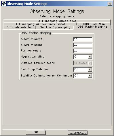
The limitation on map size is due to the stability of the band used and the associated calibration cycle. The DBS raster map size is limited to being 32x32 points. This means that maps are effectively restricted to a few arcminutes on a side in the high frequency bands of HIFI if Nyquist sampling is being used. HSpot provides a warning if the user attempts to input map sizes that are too large to fit this criterion.
This is done in the same way as for OTF maps -- see previous section.
These choices are identical in nature to the ones for the pointed DBS mode (see Section 13.2.7.1, “Dual Beam Switch (DBS) mode”).
For point-like objects where the position is less well known or where flux accuracy is needed a standard DBS cross map is used that provides a five-point cross map with small offsets (choice of "Pointing jitter" -- based on approximate pointing error of Herschel; "Nyquist" -- Nyquist sampling of beam size at the user-selected observing frequency; "10", "20", "40" -- for step size in arc seconds).
The mode is very similar to the point DBS mode (see Section 13.2.7.1, “Dual Beam Switch (DBS) mode”) with fast chop or continuum timing user choices for the mode along with the cross step size.
The time estimator interface for HIFI mapping modes is the same as for point source modes. An optimum observing sequence that fits the input user setup is found and the time it takes is estimated.
OFF measurements and calibrations are taken after one or more line-scans in the OTF maps. For long scans the time taken for a scan can be long with respect to the stability time of the observing band. This can lead to a large drift noise component to the total noise of the observation.
For mapping observations, an integer number of map repetitions can lead to large steps in the amount of time a map takes to be observed. A match between input user request time or noise may therefore not be very close. This is particularly true if a minimal amount of time is requested for a mapping observation. In this case a fast backend readout is chosen to cover the area requested in as short a period of time as is reasonable.