After the intermediate focus provided by the entrance optics, the light is split into the long-wavelength and short-wavelength channels by a dichroic beam-splitter with a transition wavelength of 125 µm and is re-imaged with different magnification onto the respective Si bolometer arrays.
The blue channel offering two filters, 60-85 µm and 85-125 µm, has a 32x64 pixels arrays, while the red channel with a 125-210 µm filter has a 16x32 pixels array. Both channels cover a field-of-view of ~1.75'x3.5', with full beam sampling in each band. The two short-wavelength bands are selected by two filters via a filter wheel. The field-of-view is nearly filled by the square pixels, however the arrays are made of sub-arrays which have a gap of ~1 pixel in-between.
The incident infrared radiation is registered by each bolometer pixel by causing a tiny temperature difference.
The PACS filters, in combination with the detectors, define the photometric bandpass of the instrument. There are in total 3 bands in the PACS photometer: 60-85 µm, 85-125 µm and 125-210 µm. The PACS filter scheme is shown in Figure 2.4 and the filter transmission of the photometer filters in Figure 3.5.
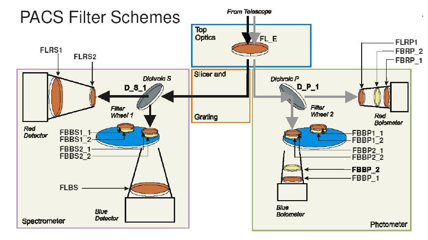
Figure 2.5 shows a cut-out of the 64x32 pixel bolometer array assembly. 4x2 monolithic matrices of 16x16 pixels are tiled together to form the short-wave focal plane array.
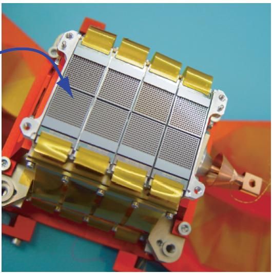
Figure 2.5. Bolometer matrices assembly: 4x2 matrices from the focal plane of the short-wave bolometer assembly. The 0.3 K multiplexers are bonded to the back of the sub-arrays. Ribbon cables lead to the 3K buffer electronics.
In a similar way, 2 matrices of 16x16 pixels, are tiled together for the long-wavelength focal plane array.
The matrices are mounted on a 0.3K carrier which is thermally isolated from the surrounding 2K structure. The buffer/multiplexer electronics are split in two levels; a first stage is part of the indium-bump bonded back plane of the focal plane arrays, operating at 0.3K. Ribbon cables connect the output of the 0.3K readout to a buffer stage running at 2K.
For science observations the multiplexing readout samples each pixel at a rate of 40 Hz Because of the large number of pixels, data compression by the SPU is required. The raw data are therefore binned to an effective 10 Hz sampling rate. After that, the same lossless compression algorithm is applied as with the spectrometer data.
The photometer operates at sub-Kelvin temperatures, which are achieved using a 3He cooler. This type of refrigerator uses porous material which absorbs or releases gas depending on the mode: cooling or heating. The use of the 3He isotope instead of the common 4He is dictated by two reasons: it is not super fluid at cryogenic temperatures below 2.2 K and it is a superior cryogen. This sorption cooler is run from a cold stage provided by the Herschel cryostat. The refrigerator contains 6 litres of 3He and can in principle be recycled infinitely, with an efficiency of more than 95% with a lifetime limited only by the cold stage from which it is run. Gas-gap heat switches, which are coupled to the Herschel 3K system with thermal straps, control the mode of operations. The evaporation of 3He provides a very stable thermal environment under constant heat load. The design of the cooler is well suited for work in space as there are no moving parts and the heat load is small.
This sorption cooler is nearly identical to the unit developed for SPIRE. It provides a stable temperature environment at 300 mK for more than 48 hours under normal observing and operational circumstances. The recycling is performed during DTCP periods, when the PACS photometer is selected for the following observing day and has a hold time of ~60h, allowing of up to 2.5 consecutive ODs of operations.